 shane.snipe
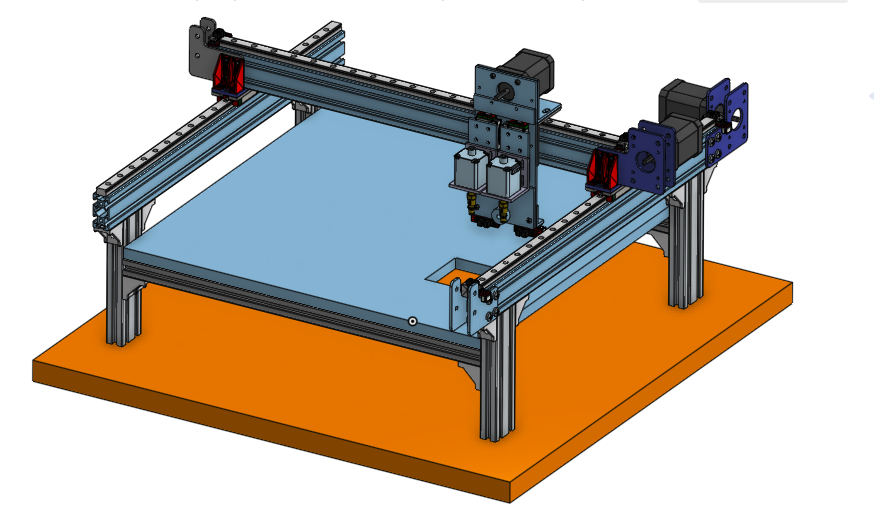
We decided to tackle the most undefined portion of the project. The files for the laser cut wooden pick and place head were in the repo but all the final pictures had the aluminum head. Of course that meant we had to find a way to start in aluminum. We had a clean slate so we tried to keep the design as clean and simple as possible. The machining is limited to cuts and holes being drilled. Here is what we have so far.
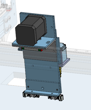 Two pcs of 2" aliminum angle are screwed to the slider. The upper one has a bolt pattern and cut out or the motor. Directly bolted to these 2 angles is the front plate. On the bottom is the bracket to mount end stop sensors for the pick and place head slides. There will be one more angle mounted on the back here to mount the camera assembly but we have not determined the height yet. Here is a picture from the front.
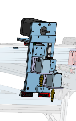
The two 9mm slides are attached and allow the heads to move up and down. They will be connected with a timing belt that goes through the middle. This means that if one head goes down the other comes up. We have determined the motor moving these was massively over specified but in the name of commonality we let it be. There is an acrylic piece above and below the rails. This is just to keep the sliders from coming off the rails. On top of the sliders there is a 3D printed part that grabs the belt. Then there is an adapter piece to connect the slider to the adapter bracket to the motor brackets. These two plates also allow the motors to be moved down a bit to get below the front plate. The motor brackets then carry the motors. These motors have hollow shafts to allow the vacuum though. The purpose of the motors is to be able to rotate the smd part after it is imaged to be able to line it up with the needed orientation on the board. Other than that, there is an idler pulley on the bottom to return the belt. We still need to design the 3D printed parts to interface with the photo interrupters on the bottom.
It think we have done well to minimize machining complexity, while maximizing rigidity and achieving the required movement.
Discussions
Become a Hackaday.io Member
Create an account to leave a comment. Already have an account? Log In.