 Bud Bennett
The PCB and components arrived simultaneously. The assembly was longer than usual due to the quantity of parts and some shorted pins on the SC70 components. I used an old 26-pin header instead of a newer 40-pin header to use up some inventory.
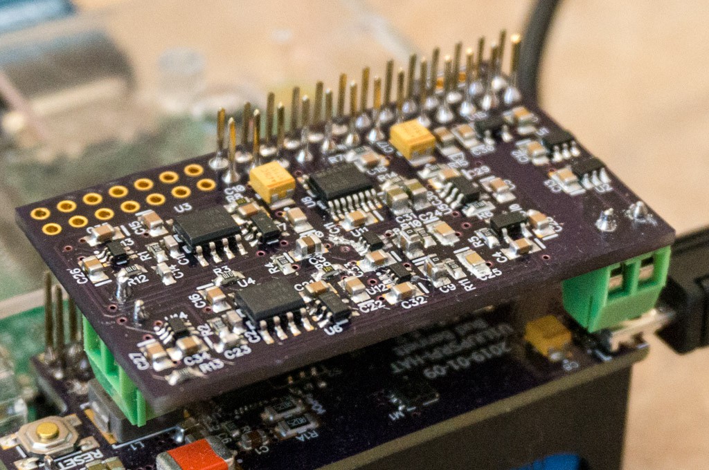
I applied power and no smoke was visible (always a welcome occurrence). When I measured the output voltages I got some weird results. The signals to the output integrator were slowly sinking toward ground and the integrator outputs weren't biased to the proper voltage. It was at this point that I took a close look at the schematic and discovered that the output integrators did not have any DC bias. I shorted out the capacitors in the demodulator, which stopped the slow drifting but the outputs still had improper voltages - like the opamps were installed backward. I reviewed the datasheet pinout for the MCP6V81 and found that there is an alternative pinout for the SOT23 package that has a "U" designation. I had unknowingly ordered the U part from Digikey instead of the standard pinout. After swapping out the MCP6V81U parts for two Gainsil GS8591 zero-drift opamps from my inventory, the board started behaving as expected.
The initial data:
Vcommon = 1.803V
VCC = 3.609V @ 7mA
Open inputs:
Vout+ = 1.823V
Vout- = 1.893V
Vdiff = -77.6mV
I was a bit disappointed that there was such a large differential offset voltage, but then I calculated the error as only 0.11pF.
With 4.7pF caps connected between EXCs and INPUTs:
Vout+ = 3.421V
Vout- = 0.308V
Vdiff = 3.119V
Swapped EXC connections to capacitors:
Vout+ = 0.231V
Vout- = 3.495V
Vdiff = -3.276V
If the capacitors were exactly 4.7pF then output voltage should have been 3.3925V. The above reading indicate that the capacitors were -5.72% low. When the offset capacitance is taken into account, the full scale readings were within 0.06% of each other.
So far so good. Now I have to figure out how to read ADC data over the SPI on the Raspberry Pi.
Discussions
Become a Hackaday.io Member
Create an account to leave a comment. Already have an account? Log In.