Curt White
The Connectome Illuminator started as a brain storming session between myself and Ting Xu, a neuroscientist at the Child Mind Institute where I work on wearable devices and sensors. We both love making art and wanted to come up with some kind of art project that would combine neuroscience and electronics - thus began Connectome Illuminator. A brain connectome is a comprehensive map of neural pathways in the brain, typically represented as a 3D model. Think of it as a brain schematic (or at least wiring diagram). They look super, super cool - you can learn more about them at the Human Connectome Project.
This is a brief video just to give you a better feel for the final product. Video and images really can't do justice though, it is stunning in person.
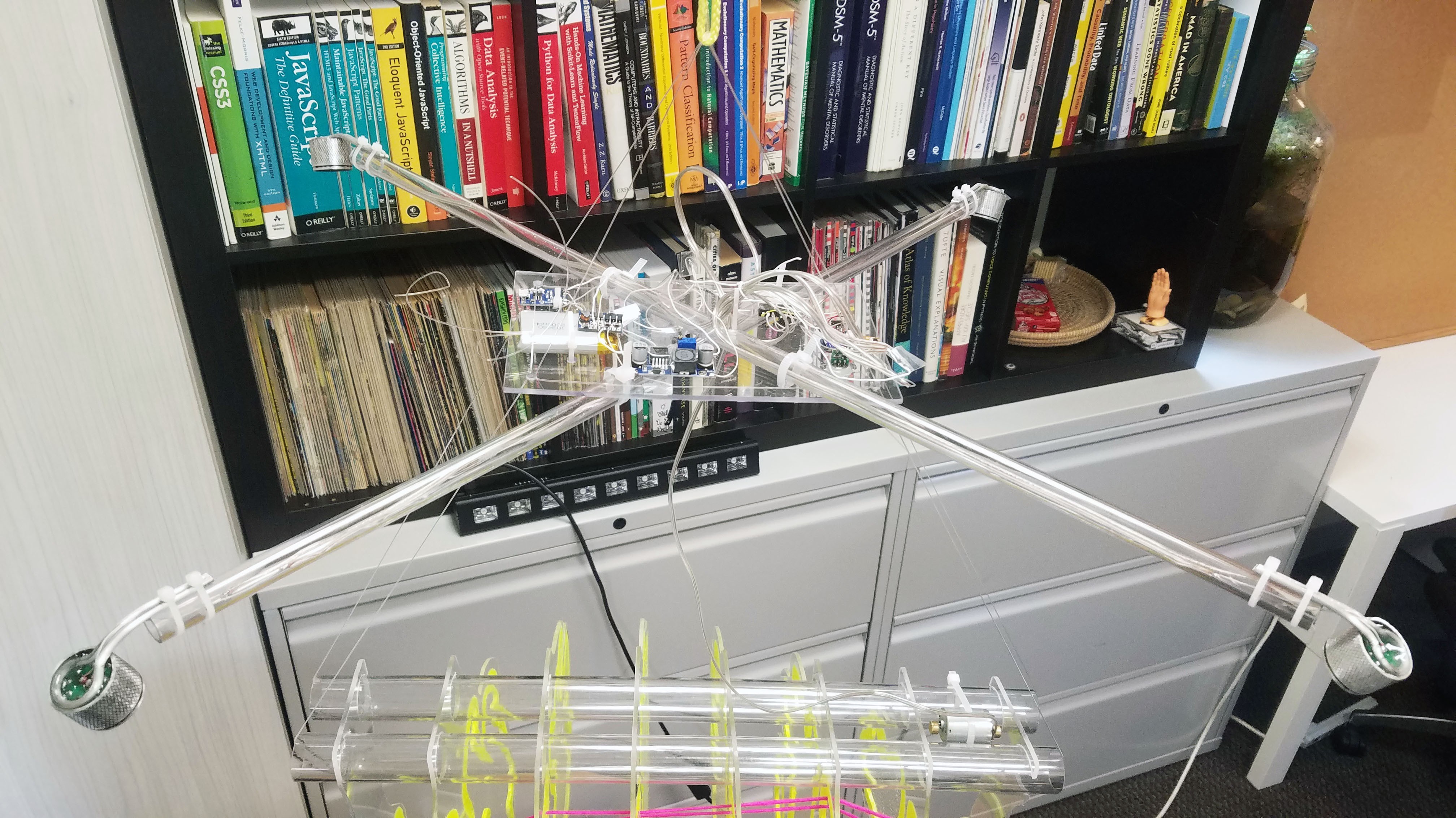
This is the ultraviolet lighting and electronics canopy that hovers about 15 inches (adjustable) above the brain/connectome model. Everything is zip-tied together with an eye towards rapid disassembly and reassembly for transportation.
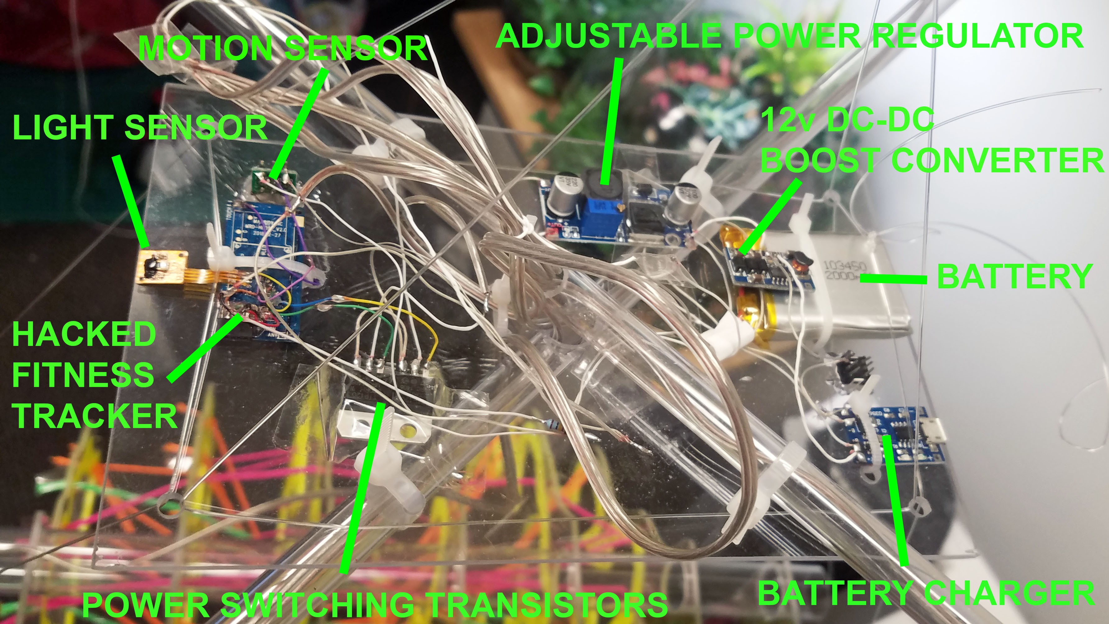
All the electronics are loaded onto a little piece of clear polycarbonate. I tried to keep everything as transparent and unobtrusive as possible to avoid distracting from the brain and connectome. The whole thing is powered by a 2000mAh Lithium Polymer battery, though it can also be powered over the USB battery charger for more permanent installations. This was all using spare parts, hence the 12 volt DC-DC boost converter.
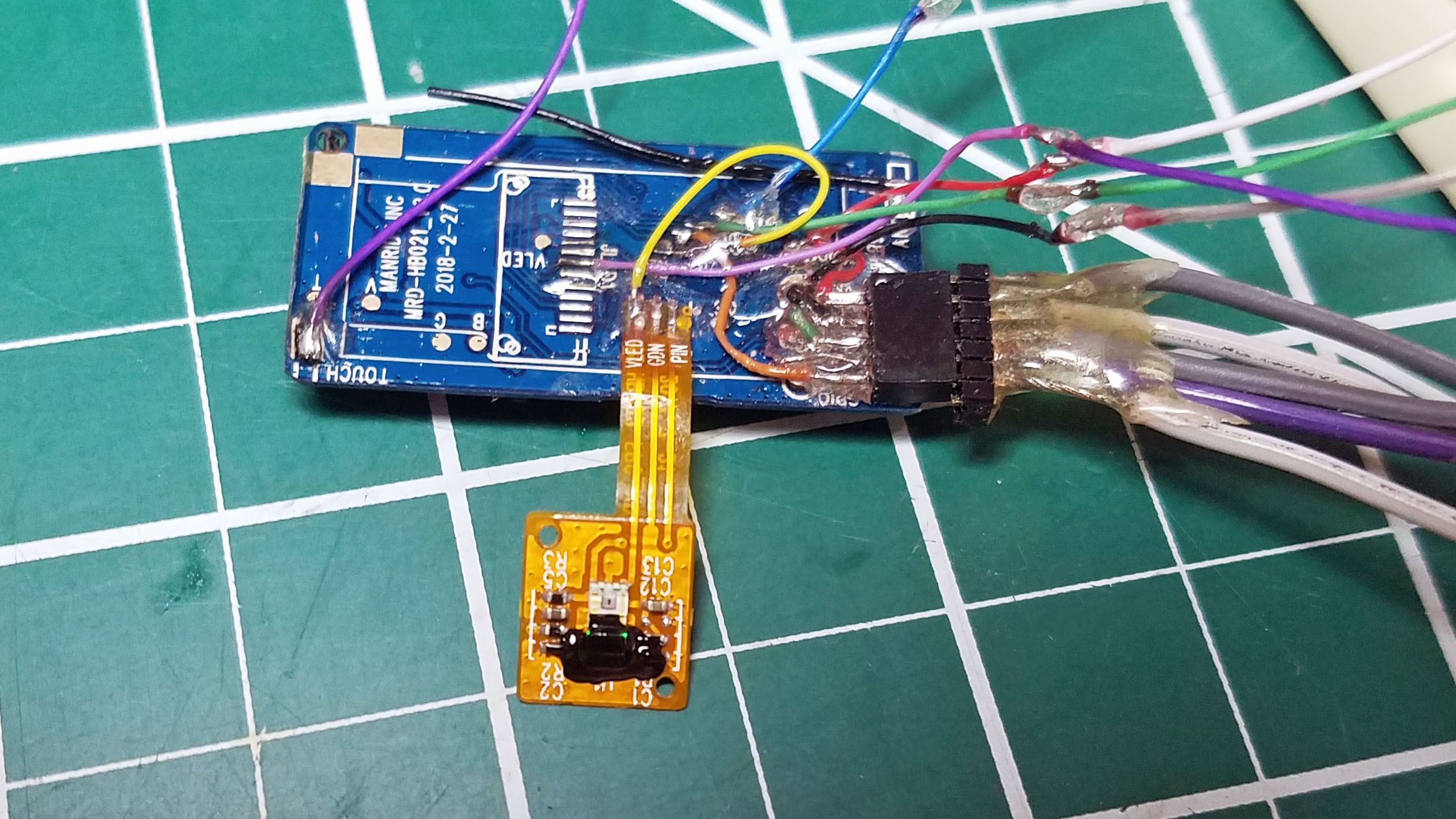
The electronics are controlled by a hacked fitness tracker containing a Nordic nRF52832 ARM Cortex M4 microcontroller. This was more a matter of convenience than anything else, I salvaged the parts from a broken Tingle gesture recognition device prototype. The PPG heart rate sensor on this hacked fitness tracker is super simple; just a green LED and photo-diode. I covered the heart rate sensor LED with a blob of black paint (you can faintly see the green LED light through the paint above) and then used the heart rate sensor photo-diode to make the Connectome Illuminator light responsive: the ultraviolet LED arrays and vibration motor start when the lights are turned out (light received by the photo-diode dips below a set threshold). The microcontroller I'm using support Bluetooth BLE so I might create a mobile app for it in the future.
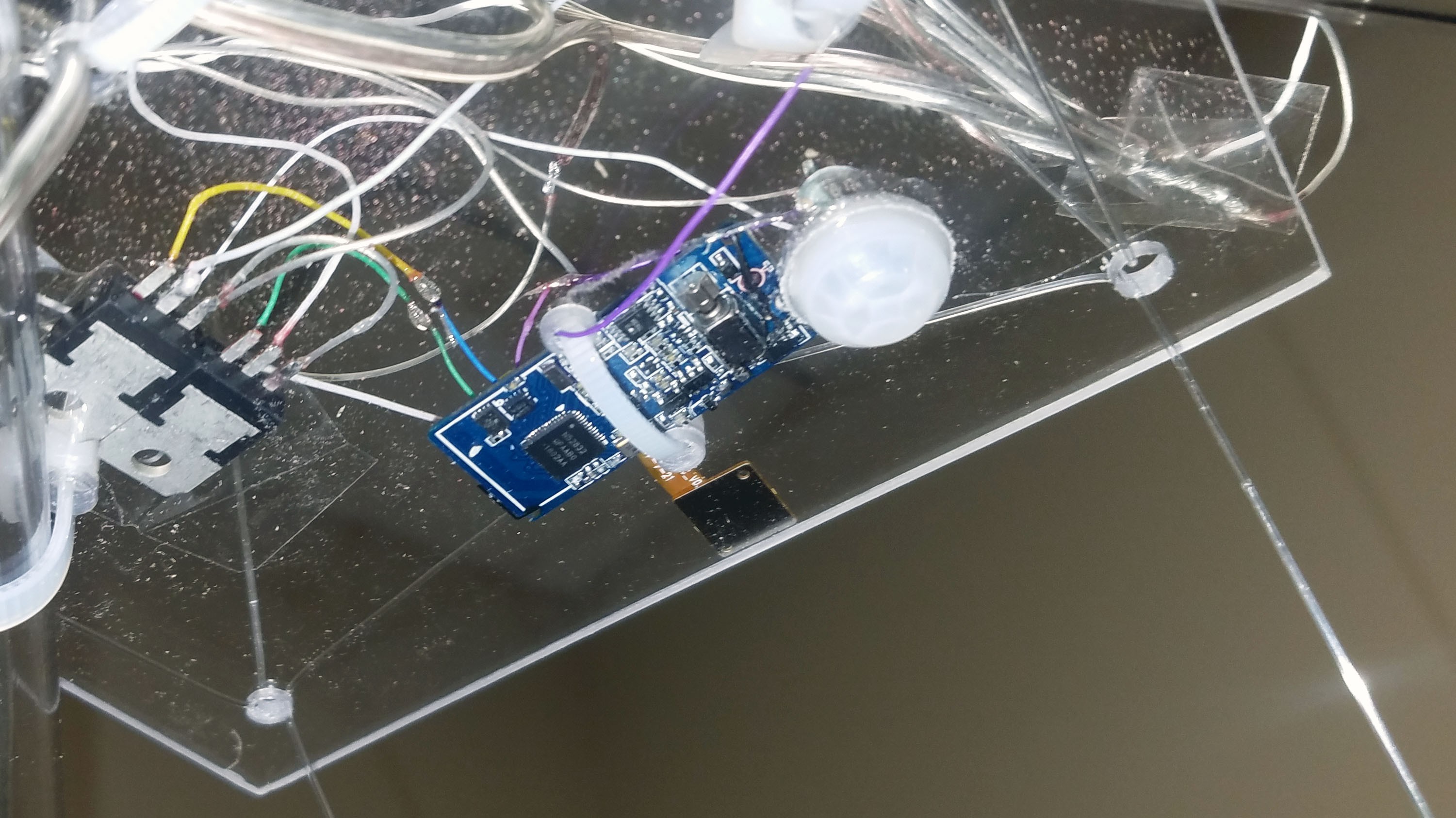
A simple thermal motion sensor (thermopile + fresnel lens array) is mounted through a hole in the polycarbonate electronics platform. The field of view is limited by the fact that it is pointed directly towards the floor. This gives it a range of about 8 feet.
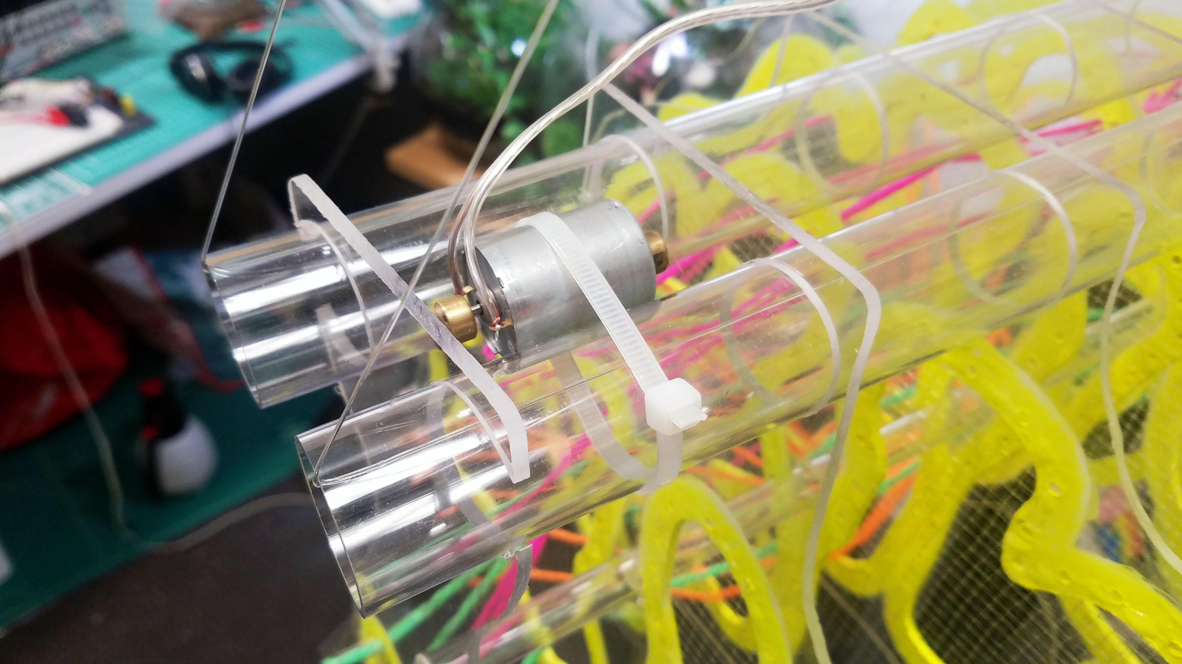
A relatively large vibration motor is attached to the connecting polycarbonate tube. Because all the ultraviolet light comes from a single direction, the vibration causes the fluorescent yarn to shimmer as if it were alive.
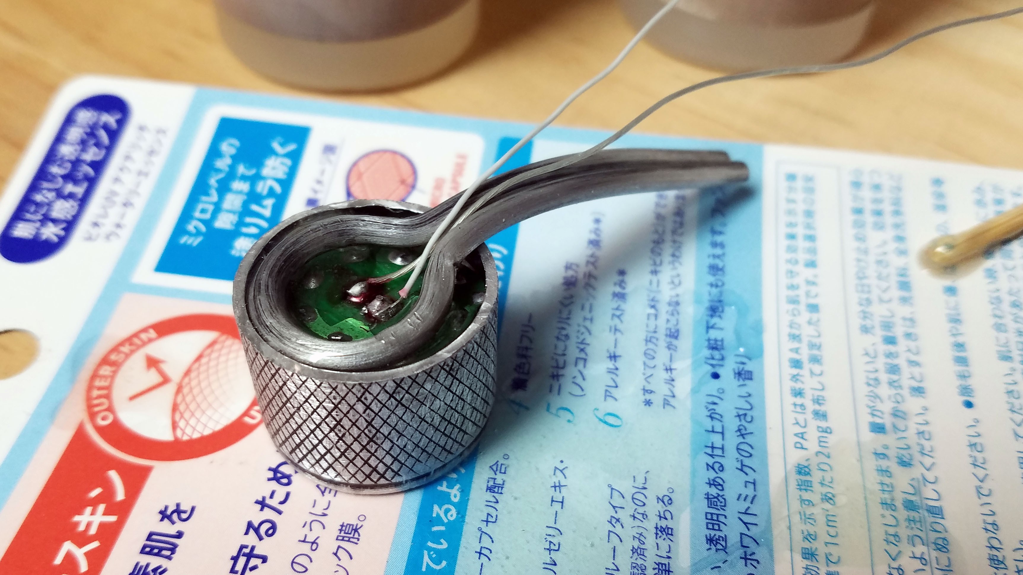
This is what the black light flashlights looked like when I was done with them. I cut off the LED containing portion and epoxied a section of aluminum bonsai training wire. The bonsai training wire is zip-tied to the polycarbonate tube canopy struts. The bonsai wire can easily be twisted to adjust the direction of the black light LEDs.
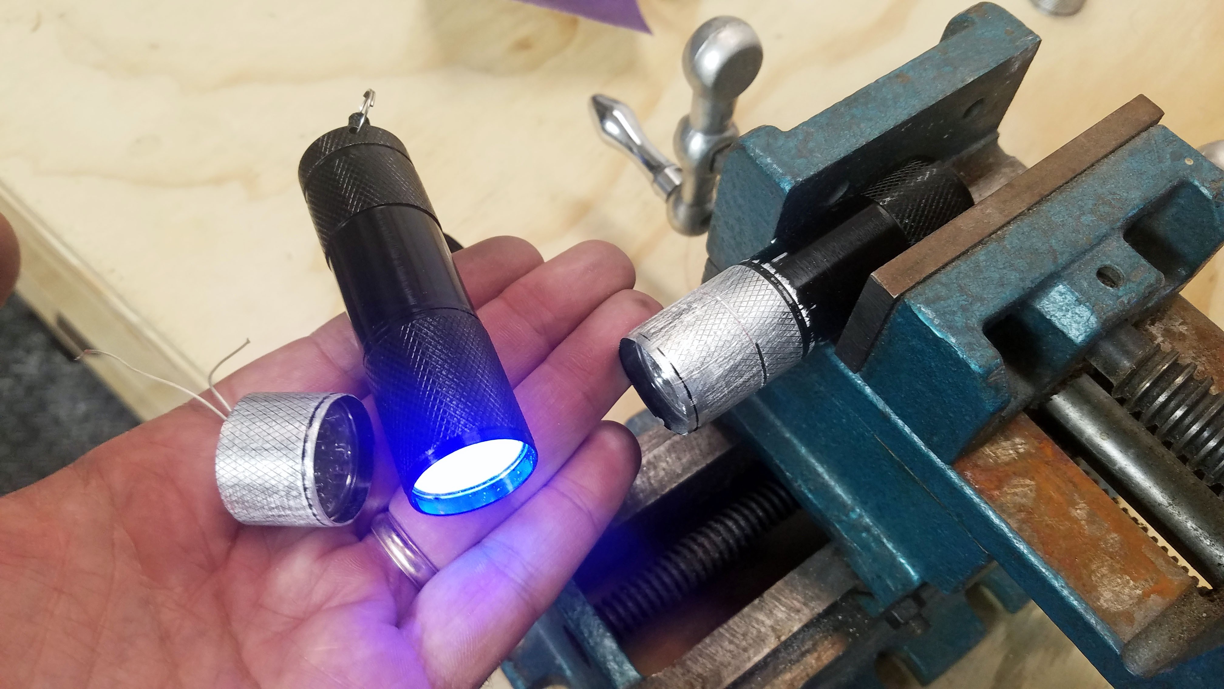
These little black light flashlights are great. You can get five of them on Ebay for $12. I wanted to integrate an ultraviolet light source into the project but I needed to get light from opposite sided of the brain model and I needed it to be cheap, light weight and low power.
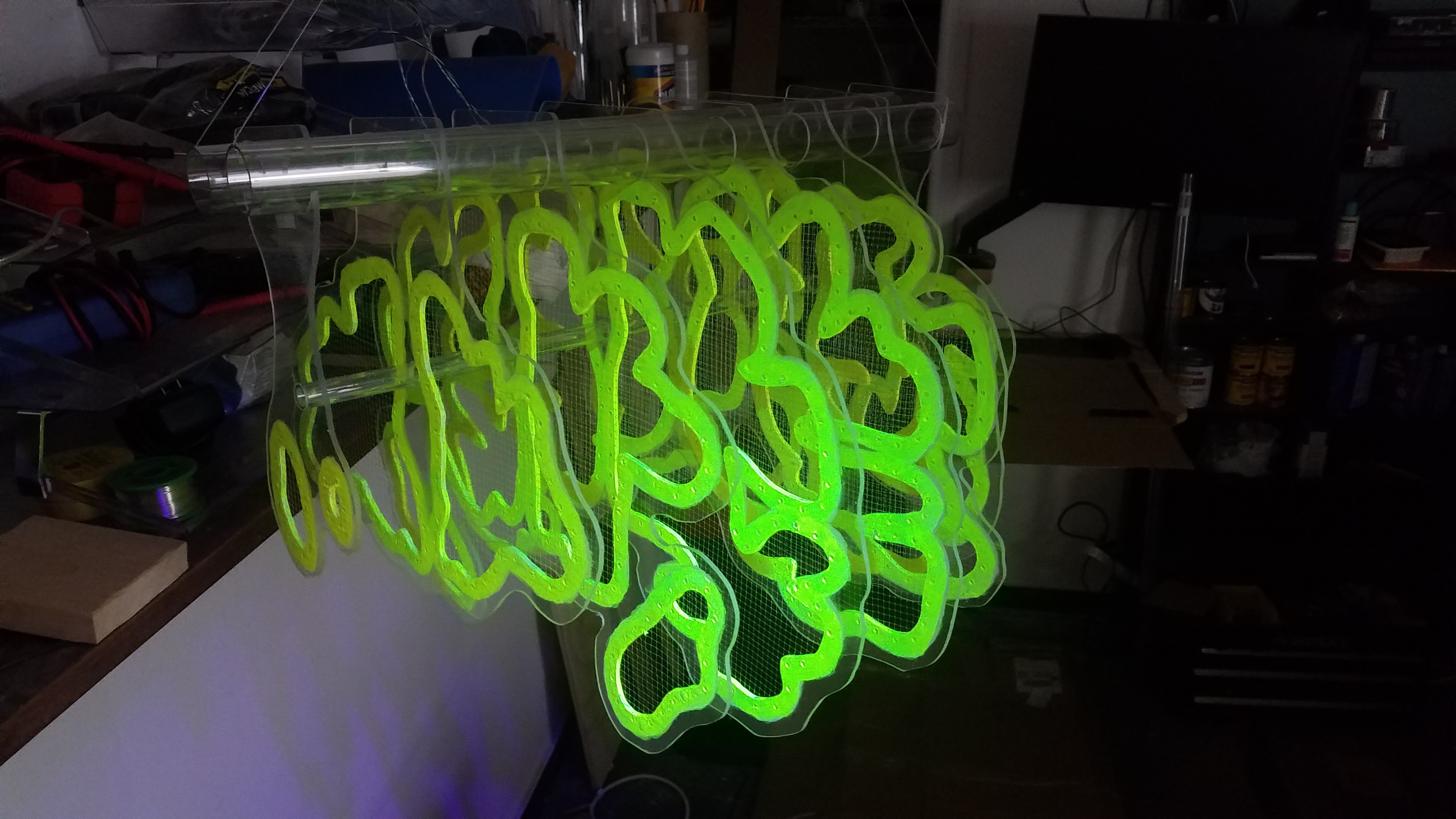
This is what the combined polycarbonate section brain model looked like when finished. Each of the eight brain sections is threaded onto three polycarbonate tubes - two big one on the top and one small tube going through the center to keep the brain sections from getting pulled together by the florescent yarn.
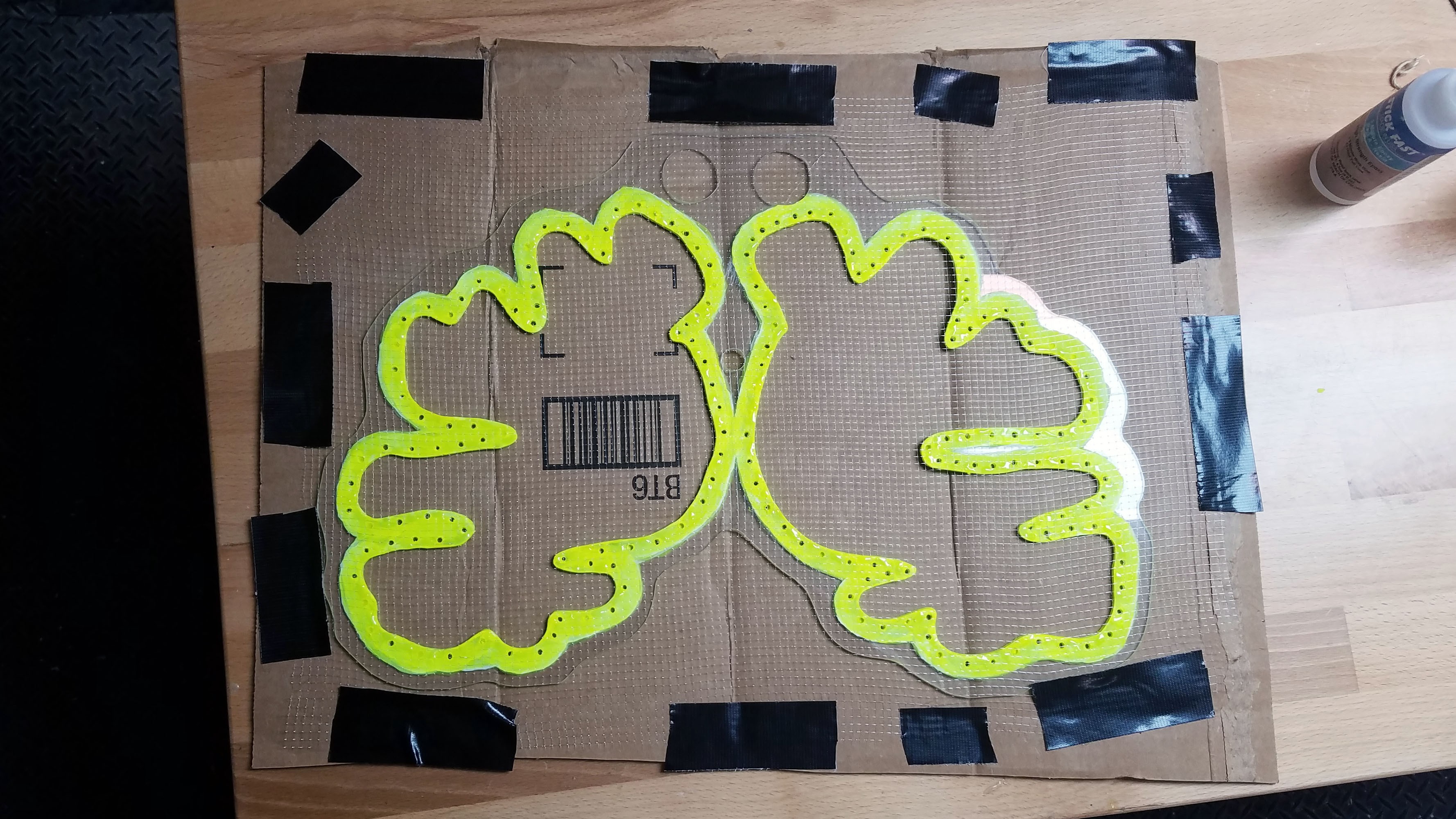
Transparent mesh was spread tightly over the polycarbonate brain sections and then glued in place with epoxy. The interior edge of the brain sections were painted fluorescent yellow.

The interior edges of the polycarbonate brain sections were drilled and painted with a white primer. The holes are for tying off the ends of fluorescent yarn used to depict neural pathways.
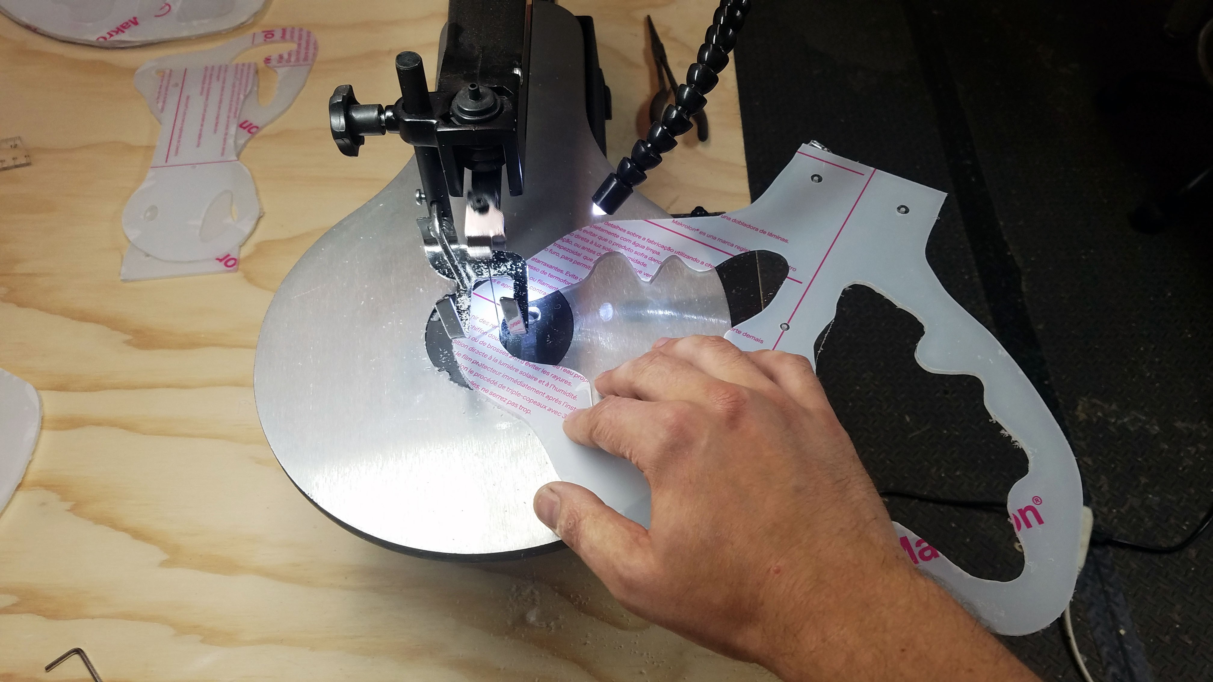
The 3D model generated brain section images were stenciled onto sheets of clear polycarbonate plastic. I then used a scroll saw to cut out negative space for the brain and the rest of the section body. I included three holes in each section for polycarbonate tubes which hold the overall Connectome Illuminator together. Originally I was going to laser cut Plexiglas which would have made the whole project much much much easier. In the end I decided that because polycarbonate is so much stronger I could substantially decrease the overall weight by using thinner sheets of polycarbonate.
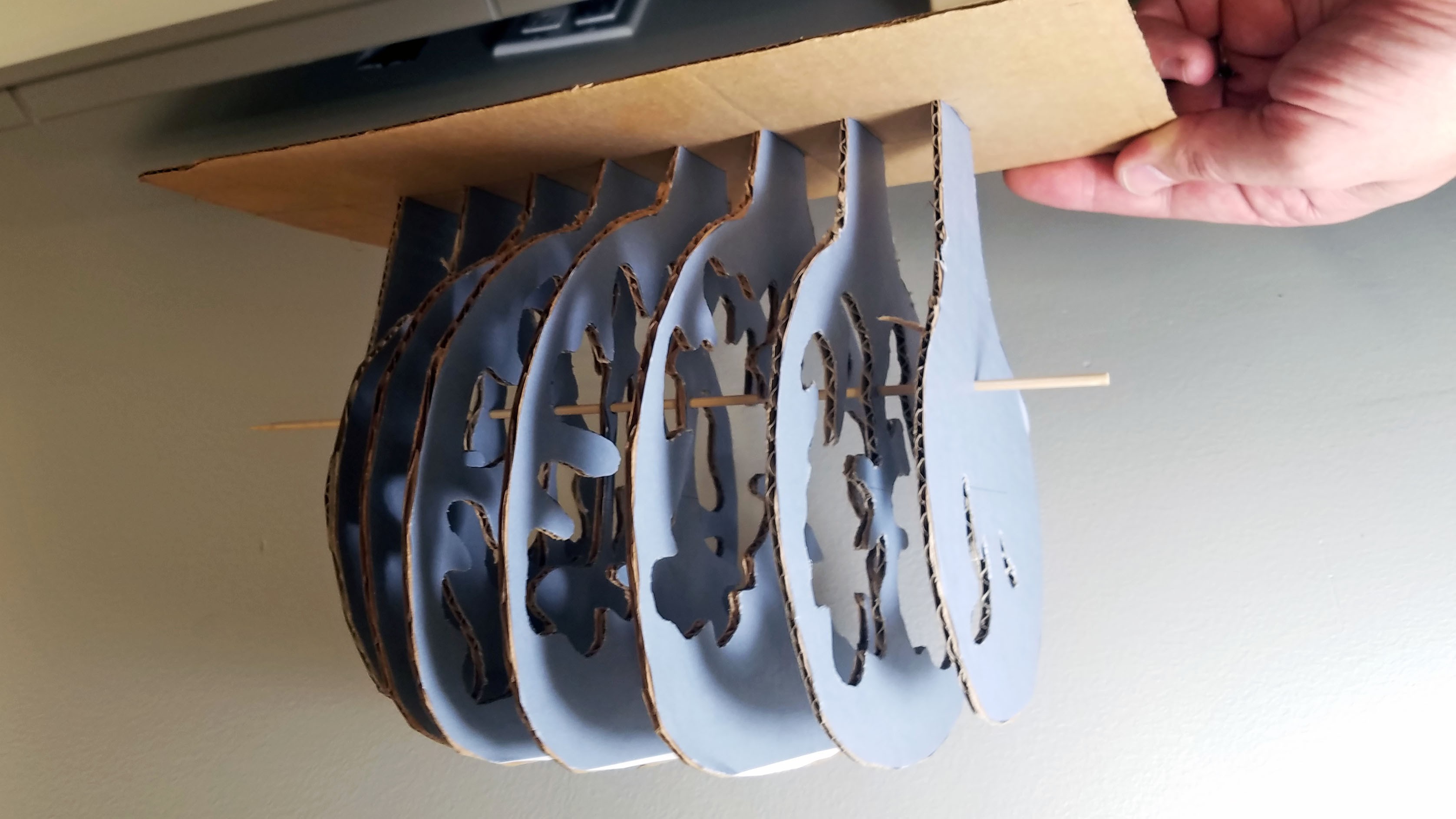
I created a cardboard mockup of the Connectome Illuminator as a proof of concept. and to get feedback from Ting on project progress.
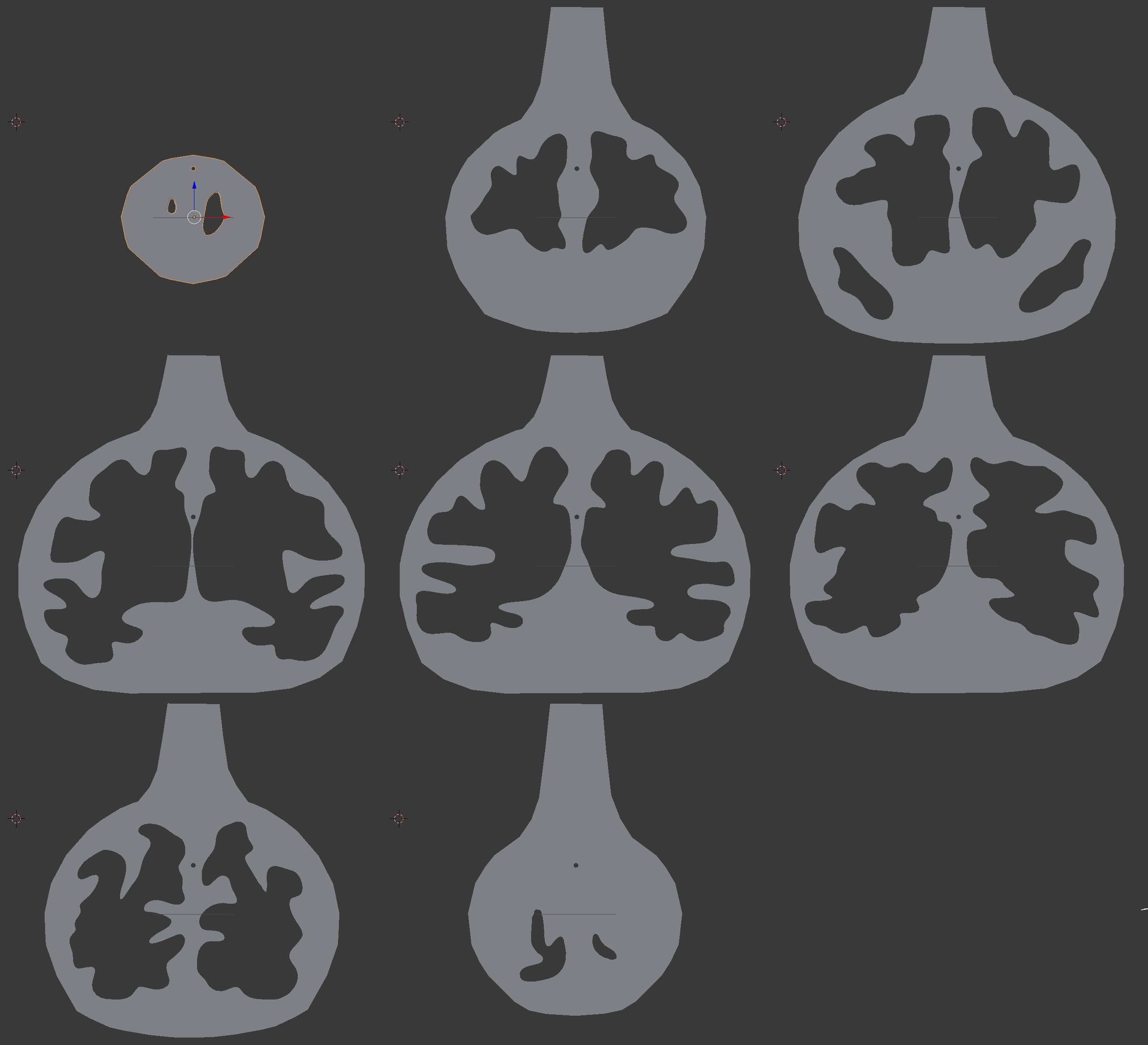
These are the eight brain sections generated from Ting's 3D MRI model and eventually produced in clear polycarbonate form.
This is after subtracting the brain model from my eight 2D section models.
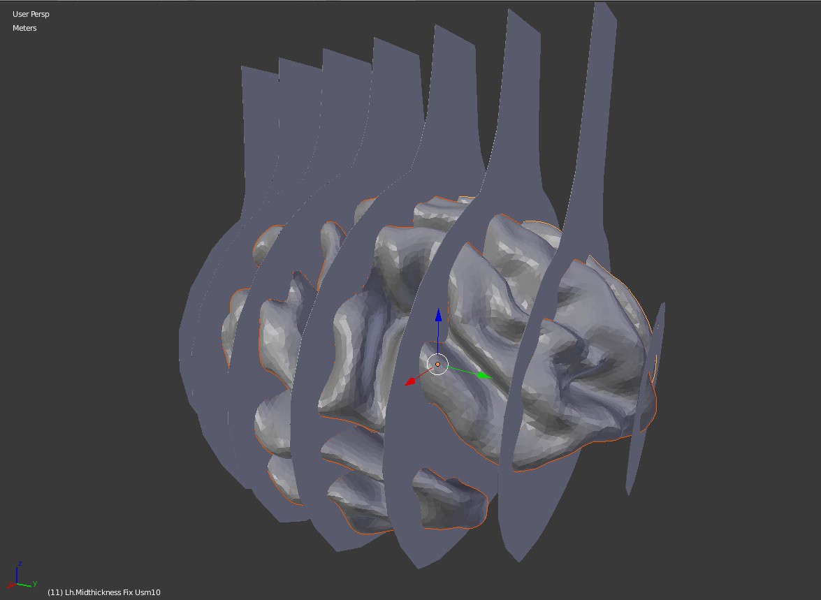
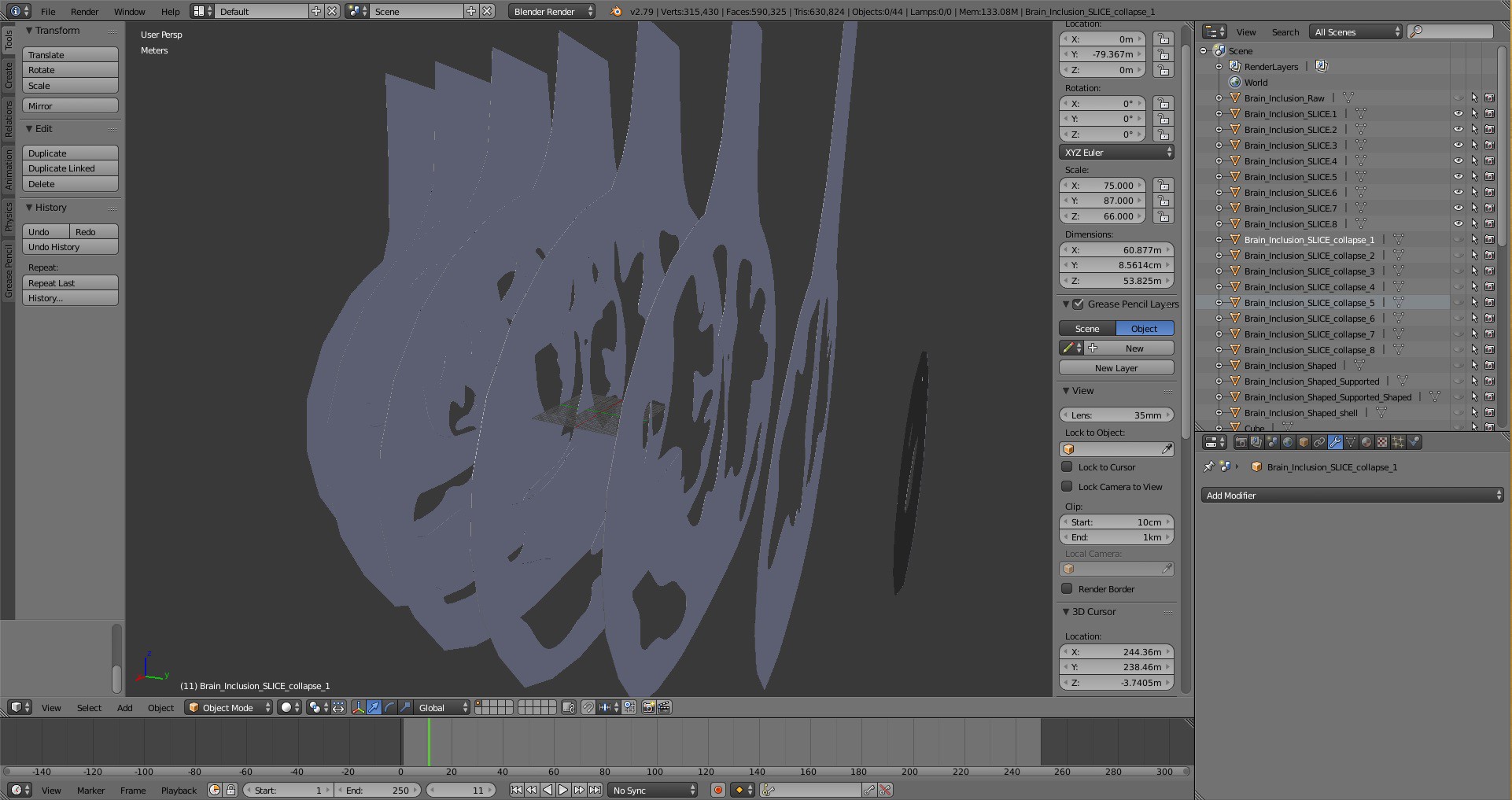
I created 2D representations of the eight plexiglass sheet section and spaced them evenly across Ting's 3D brain model.
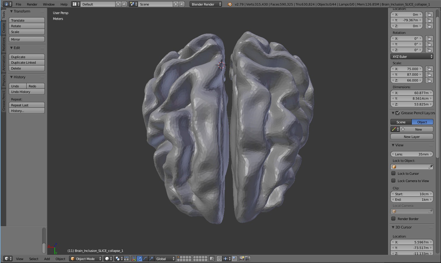
The Connectome Illuminator is based on a 3D MRI scan of Dr. Ting Xu's brain (above). The Connectome Illuminator IS Ting's brain. You can view the 3D brain model live HERE .