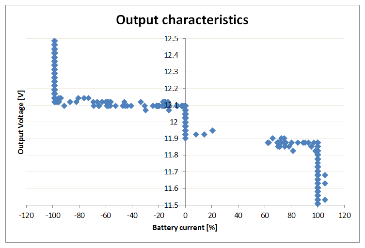
I connected the converter to 4 Li-ion 18650 cells and its output to load resistor parallel with regulated power supply. This way a could change the amount of load put to converter both sourcing and sinking current. To keep the microcontroller "independent" I powered it and mosfet driver from 5V USB-port through the rs-232 converter to which the microcontroller was reporting internal state. Bellow is the is the plot of self-reported output voltage vs battery current. The two modes of operation can be seen in which converter sinks current when the voltage is above 12.1V and sources current when voltage is bellow 11.9V. At certain level the converter goes into maximum current protection and the converter switches to constant (battery) current mode.
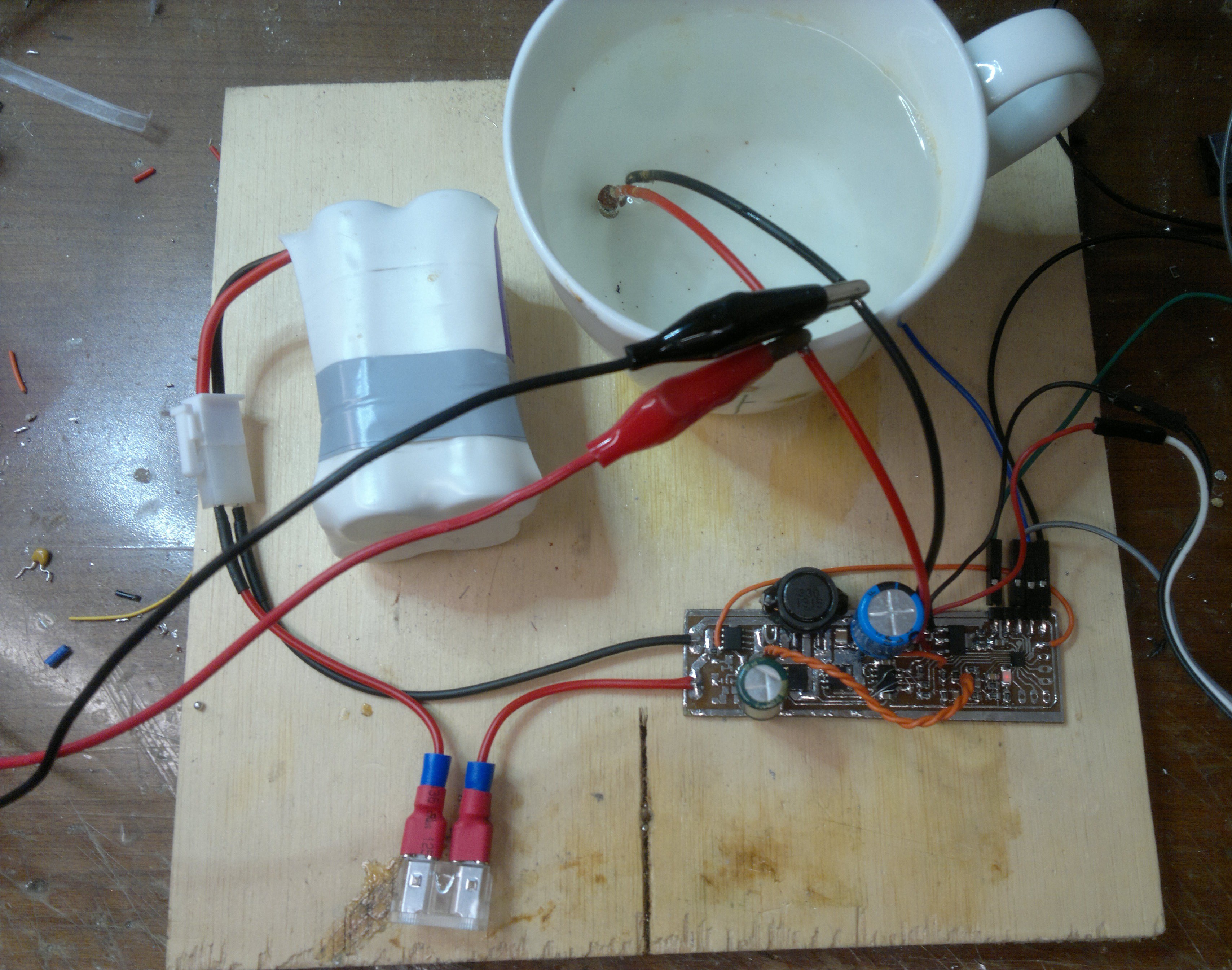
The test setup:
Discussions
Become a Hackaday.io Member
Create an account to leave a comment. Already have an account? Log In.