Ancient commercial product was quite simple and also all of schematic were released for fixing/repair purpose. (Today's product is ultra complex and not so many people will be happy even iPhone releases full schematic).
By reading the schematic, I've put two hack for my retro radio (ONKYO OS-195).
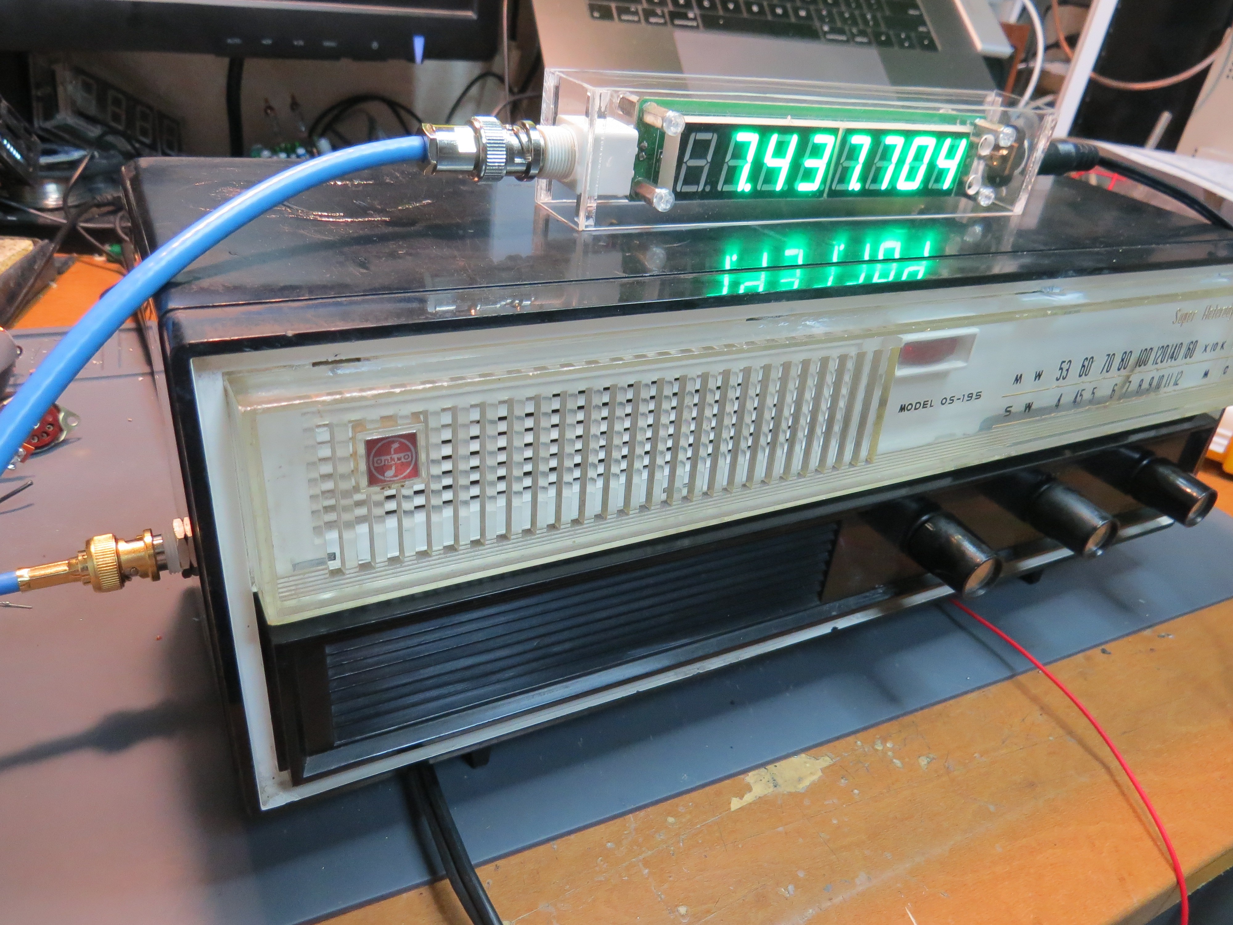
- Digital frequency meter

By measuring local oscillator frequency, we can guess the receiving frequency (one concern is, whether it is exact 455 kHz IF or not..). My frequency counter has a function of IF frequency subtraction, and putting one terminal from local oscillator part, YES, now the reception frequency is digitally readable!
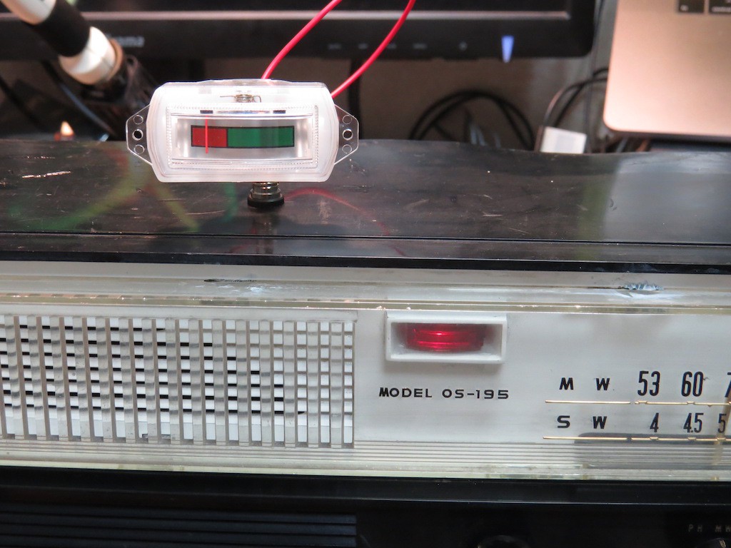
- Signal strength meter addition
It is just fun to see the reception signal strength monitor. Mostly this is done by Magic Eye but the enclosure does not have enough room for it. (and also I wonder how to get heater voltage, because it is series connected trans-less heater driving..)

So this time I added one 3.5mm jack terminal on the top of the radio, which is connected to AGC voltage portion. This meter is just showing the AGC voltage, leading to S-meter!
 kodera2t
Discussions
Become a Hackaday.io Member
Create an account to leave a comment. Already have an account? Log In.
Hahaha, I understand totally the hacker desire to measure everything. I used to have computer load, throughout widgets, VU meters, spectrum displays, and so forth on my desktop until I realised I wasn't paying attention to them anymore.
You could possibly spare a few volts at the bottom of the heater chain unless it's a directly heated cathode magic eye tube.
Are you sure? yes | no