kodera2t
-
LED blinker circuit (non-stable vibrator)
06/09/2019 at 10:02 • 0 commentsAs per some request, I will show the circuit of LED blinker.
![]()
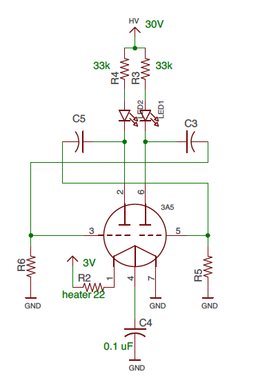
The pairs of C3, R6 and C5, R5 defines the time constant and that defines blinking frequency.
-
Usable (I would not say practical) superheterodyne circuit is fixed...
06/09/2019 at 09:49 • 0 comments![]()
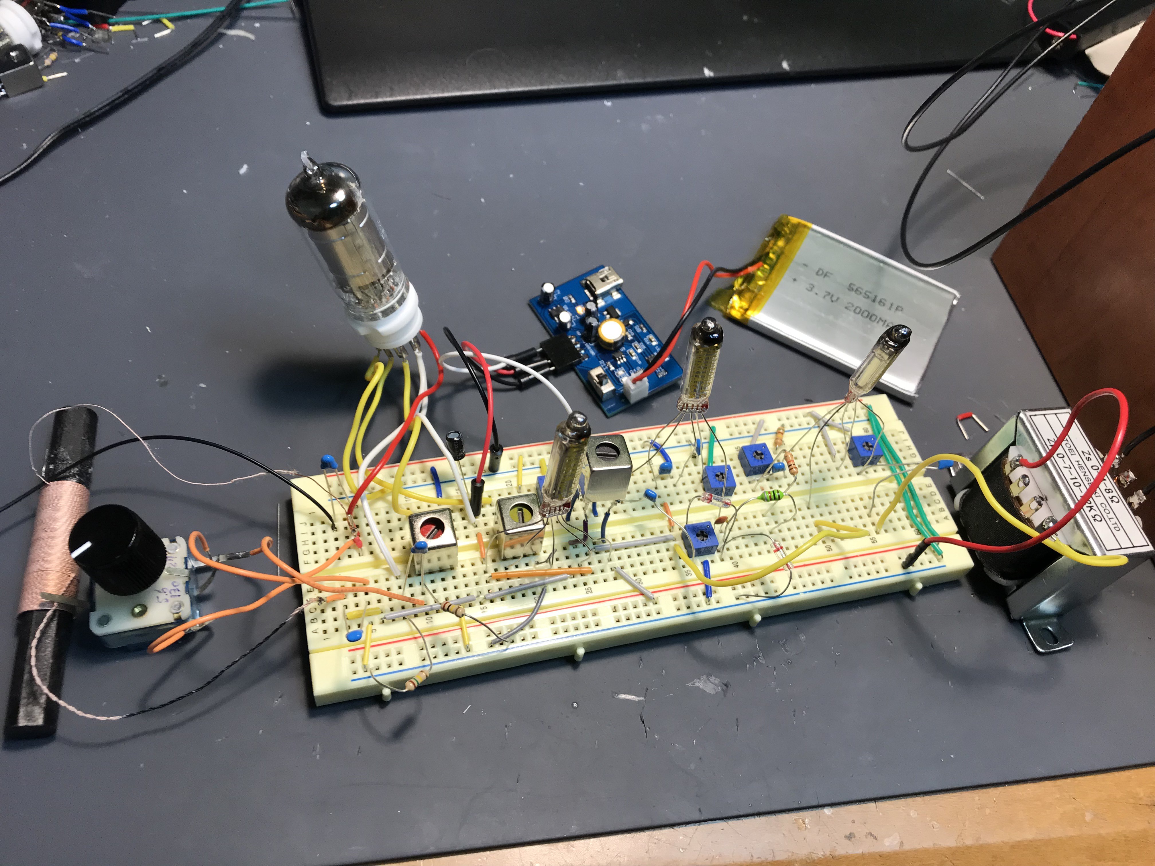
Before I presented the superheterodyne type but this time I've fixed for more usable shape. I've wanted "direct speaker drive" (withOUT transistor active speaker) to enjoy "pure vacuum tube sound" but three battery driven tubes were not enough to do it (or my design is not so good.)
So this time I simply added audio amplifier at the end of circuit.
![]()
This the the whole circuit. Indeed, super simple compared to my 48kHz USB DAC, but works very cleverly. The first tube (left end) is 1R5 heptode working as local oscillator and frequency mixing. The oscillator coil is the one for transistor circuit (Red coil). After passing 1R5, 455kHz signal goes to 6418 subminiature tube amplifier, and goes to reflex circuit, which demodulate 455 kHz AM signal to audio, and finally the last tube is simply audio amplifier and goes to speaker through impedance trans. Actual operation is as follows. Indeed, it does not still exhibits so high-sensitivity but anyway speaker driving pure vacuum tube superheterodyne radio is done!
-
Most useless application? LED blinking by 3A5
06/08/2019 at 12:17 • 2 commentsI like 3A5 so much, for its mellow and brilliant sound through triode. But this time, the application may be most useless one. It's LED blinking.
It's blinking period can be determined by C-R discharging time constant. Indeed, we can simply regard Grid-Gate, Plate-Drain, and Kathode(3A5 is direct heated tube so it is GND of heater)-Source between vacuum tube and FET. The big difference is heater power requirement and high voltage requirement. Actually "gm" is common in both FET and vacuum tube!
-
I got a useful tool for vacuum tube experiment.
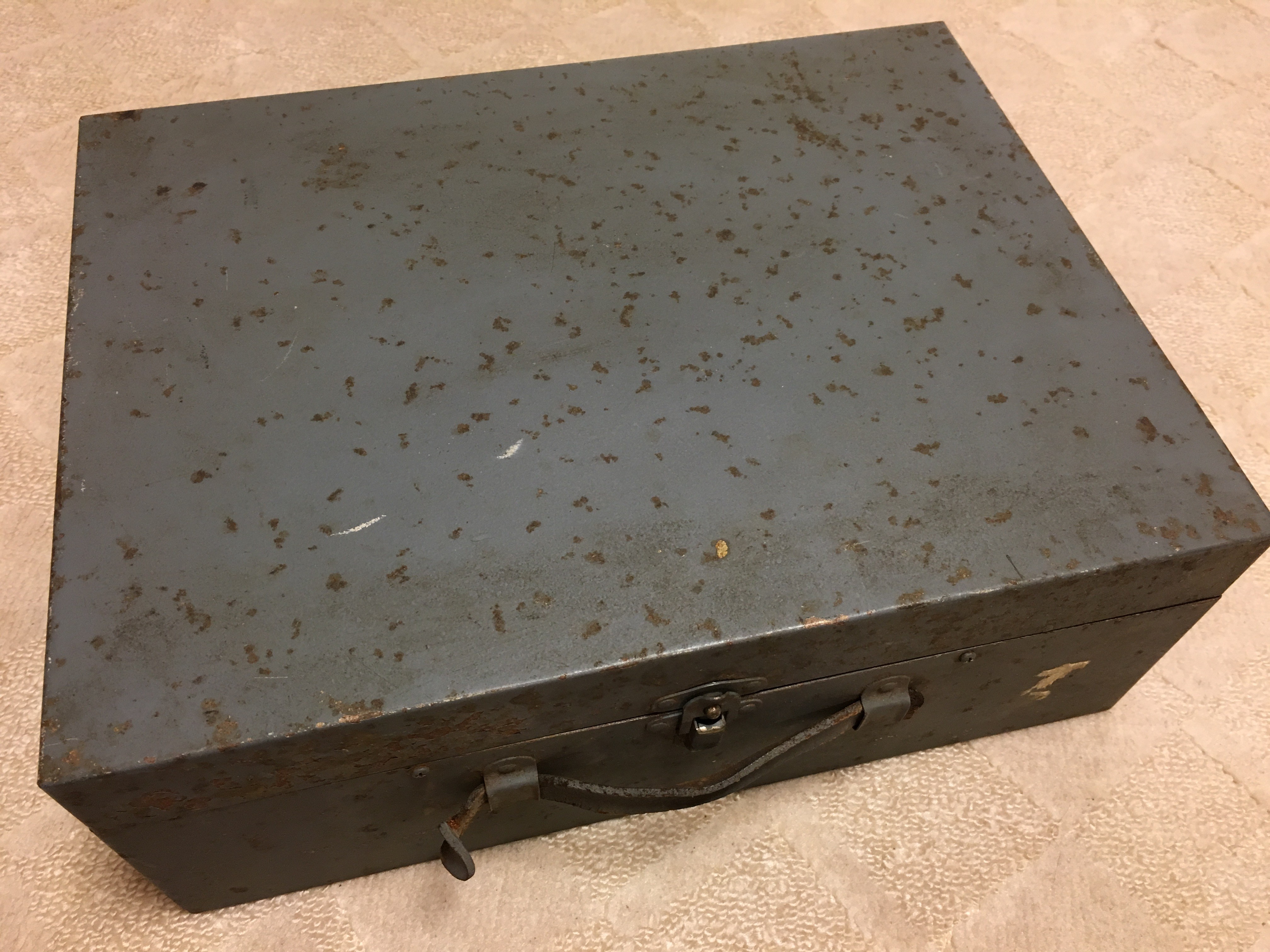
06/07/2019 at 13:14 • 4 commentsI got one instrument in old metal box...
![]()
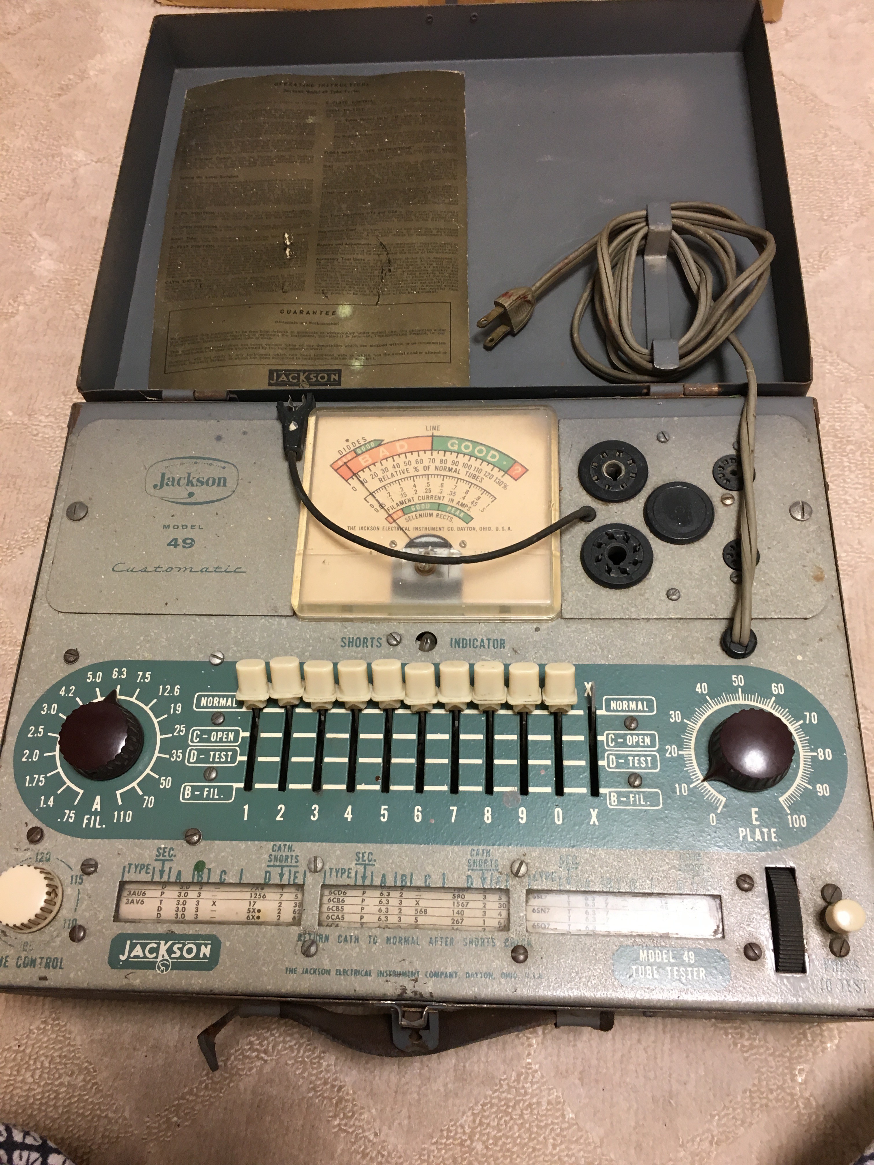
It is made in 1950. It is not so heavy and inside it....
![]()
It's vacuum tube tester made by Jackson. I know more expensive one can measure gm in addition to emission, but they are very expensive. This time I got this one just by 10000JPY. Actual operation example is introduced in the following movie. So now I can check if the tube is dead or live!
-
Shortwave reception is difficult? NO and YES..
06/07/2019 at 12:31 • 0 commentsIndeed, the case of "reflex radio", receiving frequency is simply defined by the resonator consisting of variable capacitor and ferrite bar antenna. Then, if we change ferrite bar with proper inductor resonating shortwave with variable capacitor? Here is the answer.
![]()
I just wind wires on several ferrite bar. I have a strong tool of inductance measurement...
And I just replace it with ferrite bar in Nuvistor reflex radio. Yeah, shortwave reception is not so difficult. BUT separation is ultra bad. Indeed, I can listen the mixture of DPRK and China (CRI) and also AFN (810 kHz) simultaneously. Superheterodyne or double tuning in order to get more sharp separation is indispensable for "honest" shortwave radio..
-
#5 3-tubes superheterodyne Radio
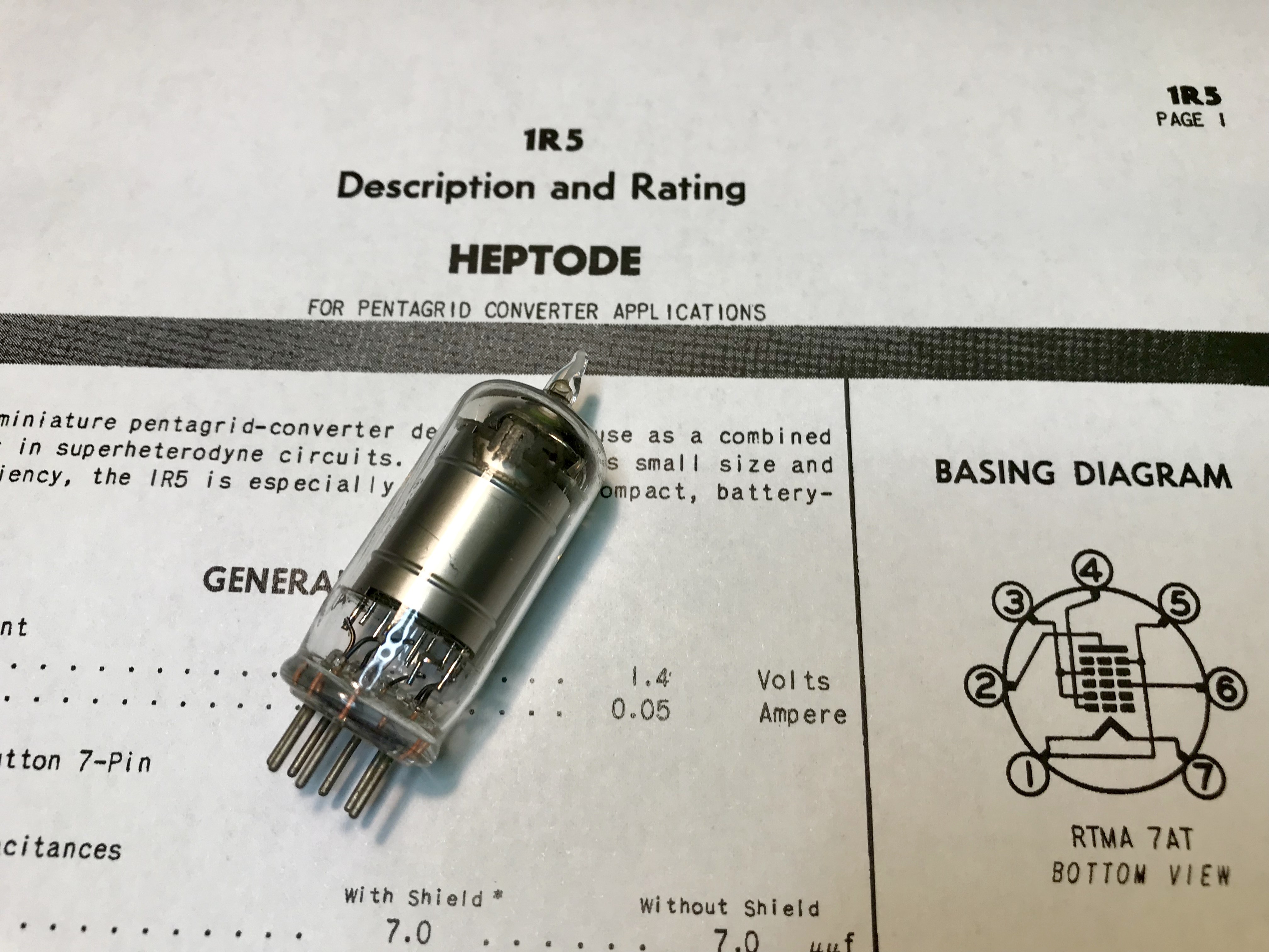
06/02/2019 at 09:01 • 2 commentsI've got IR5, it's "heptode"=7 electrode vacuum tube. The structure is two additional electro-inserted pentode. Two additional electrode can work as local oscillator and as a whole, this tube can serve "frequency conversion". More exact explanation is available at wikipedia.
![]()
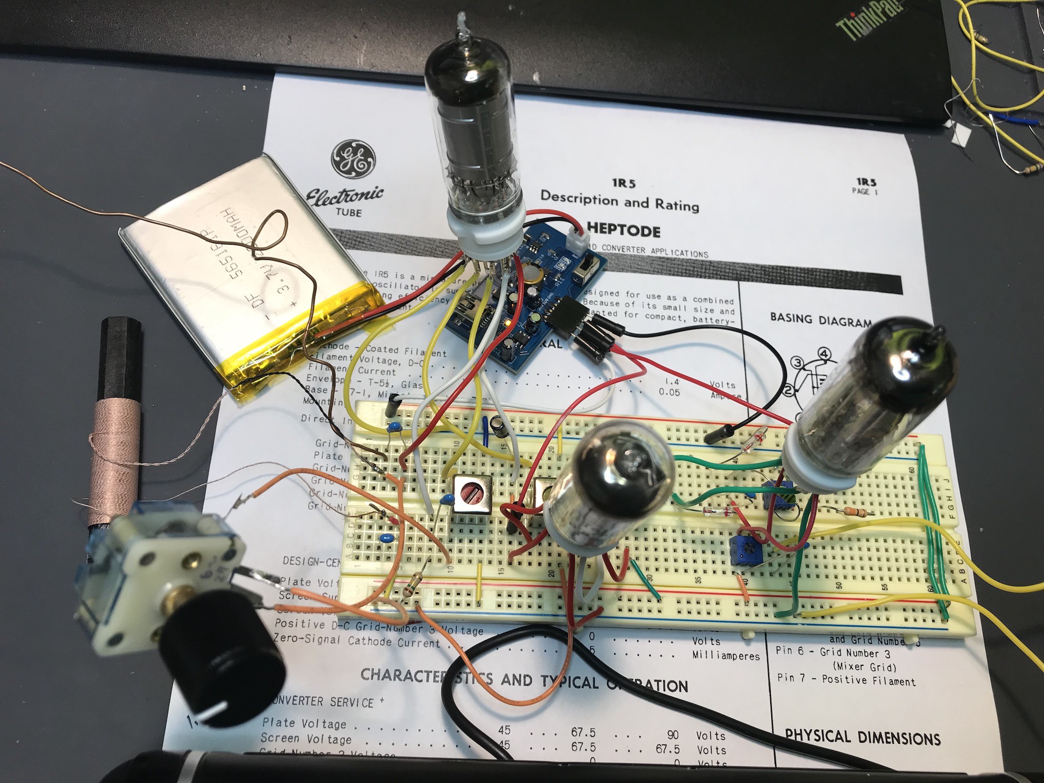
More than 40 years ago, pocket battery radio was made with this tube and 1R5 was widely utilized. I quickly wired "breadboard superheterodyne radio".
![]()
IFT (intermediate frequency transformer) for vacuum tube is hard to find, so I simply use ones for transistor expecting it will work as I expected. (the difference between vacuum tube trans and transistor is current tolerance. Thin wire in Tr trans may burn out for high current, but it will work in battery tube,,, I hope). The configuration is, IR5 for mixer/local oscillator, 1T4 (later I changed it 1L4) for IF amplifier, and 3A5 for IF amplifier and AF amplifier.
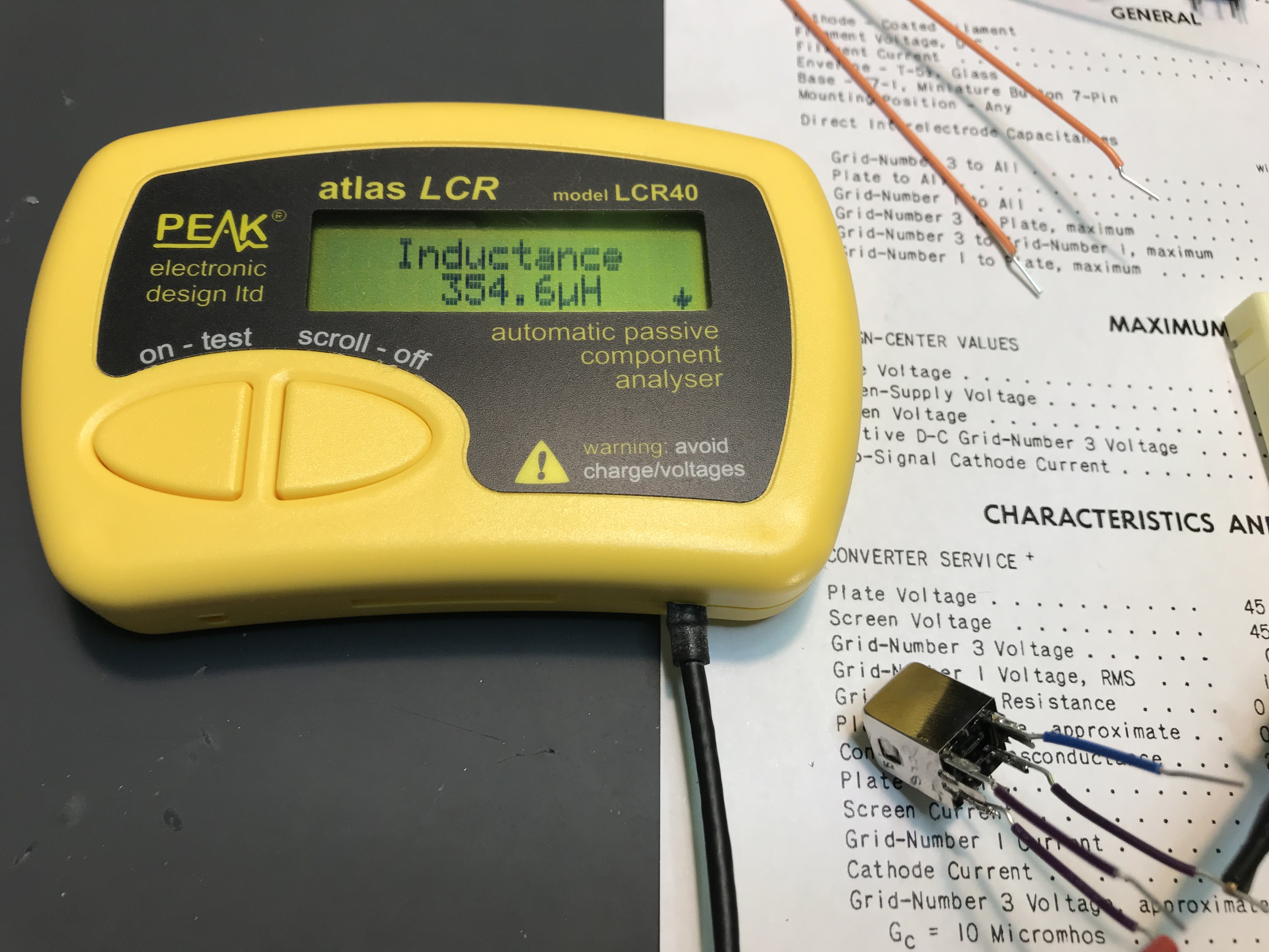
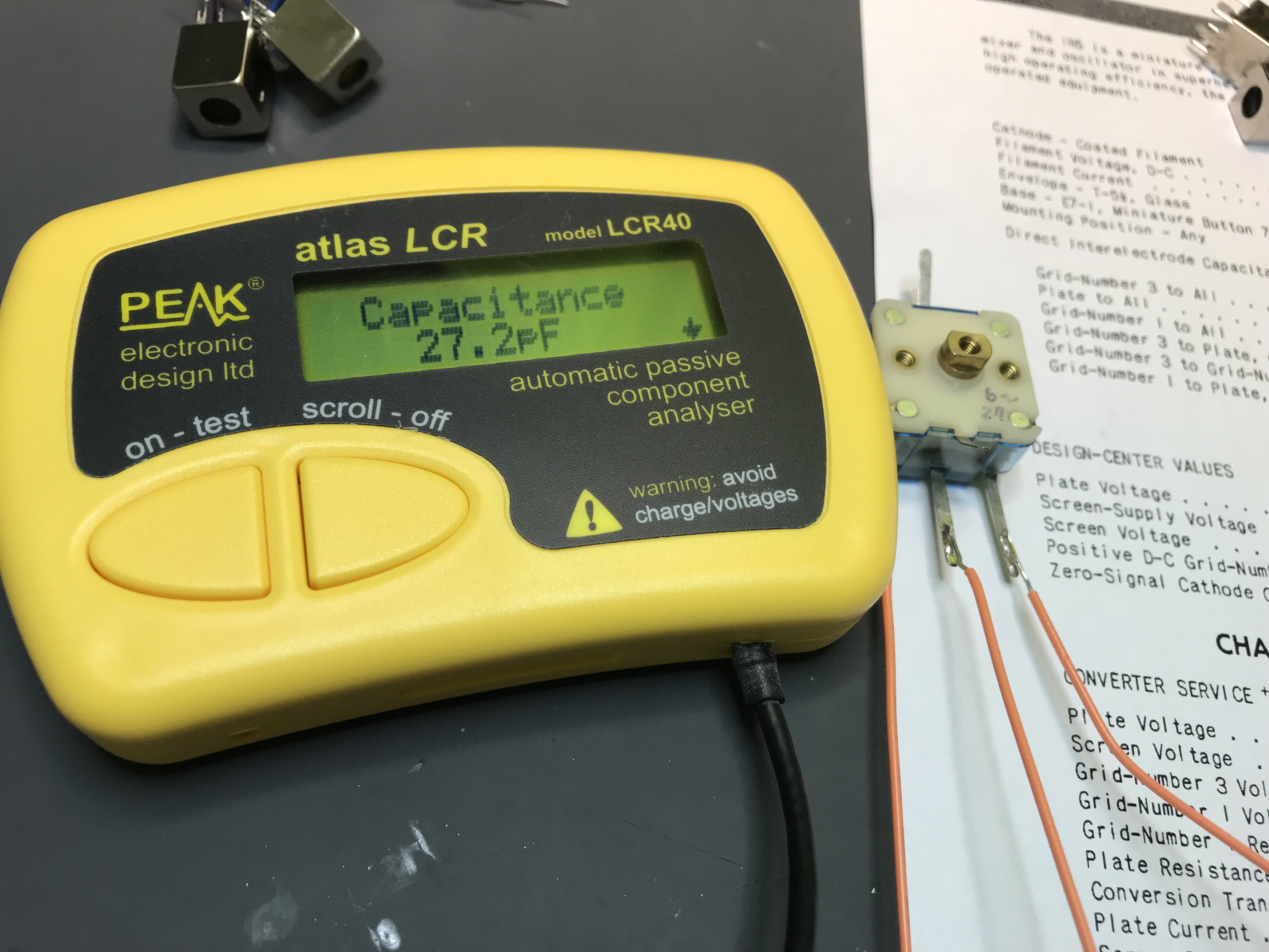
One thing I had to do is check capacitors of unknown variable capacitor and IFT.
![]()
![]()
It is quite important to know values for completing circuit. Otherwise we have to struggle in the complete dark (and will lose)
.... And finding parameters and making......
And... it works as above picture!
-
#4 diode-pentode composite tube (1U5) radio
06/02/2019 at 01:52 • 0 comments![]()
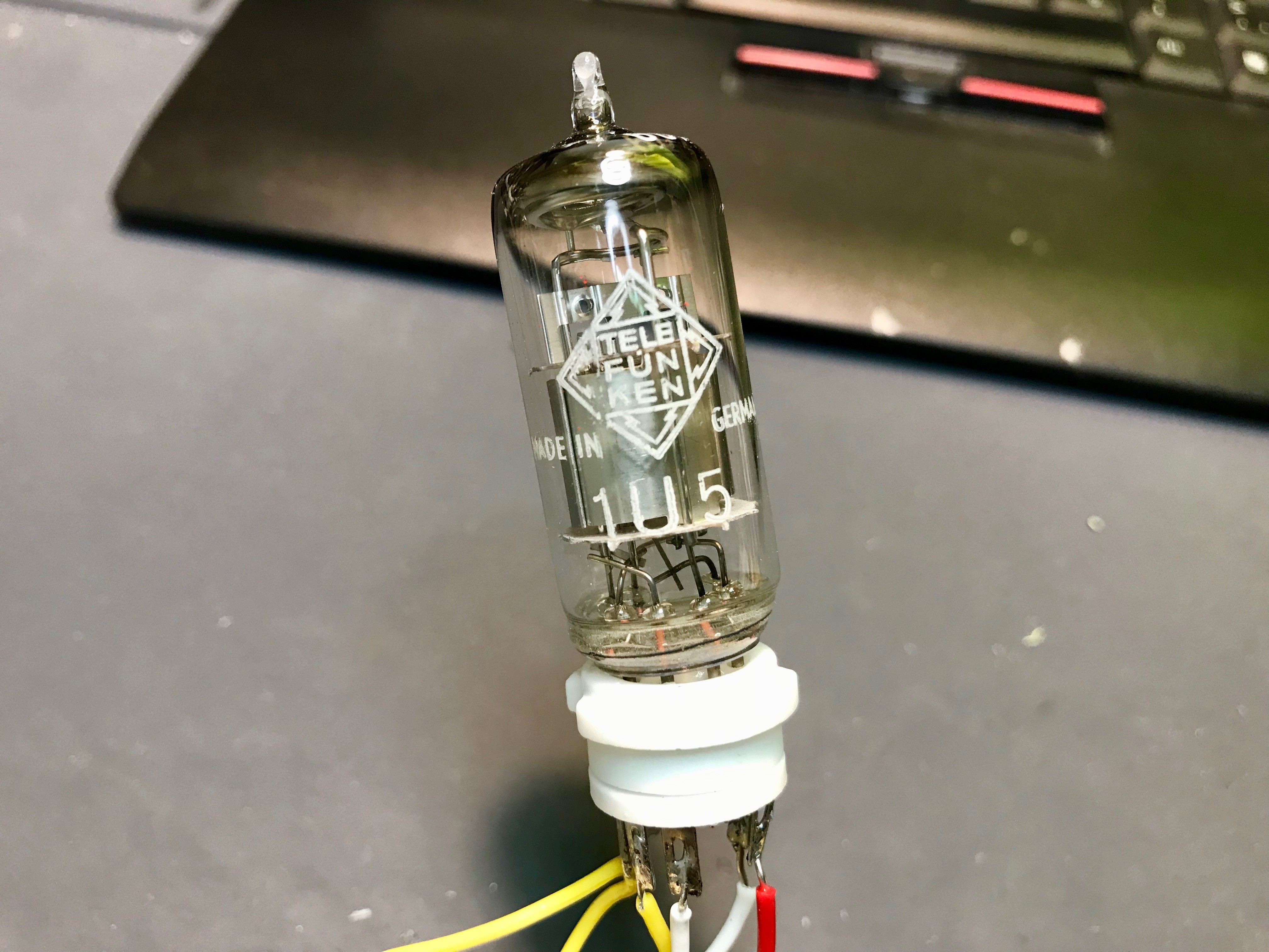
In the vacuum tube era, there was lots of "composite tube" in which two or more elements are composited in single tube. One example is 1U5, diode-pentode.
![]()
Of course, "diode" is not semiconductor but its real meaning device. The above pinout image shows diode between #4(plate:anode of diode) and #1 for cathode of diode. As same as semiconductor diode, vacuum tube diodes are application specified (power rectifier or RF rectifier) and the one in 1U5 is for RF rectifier. So utilizing this diode, we can make "pure vacuum tube radio".
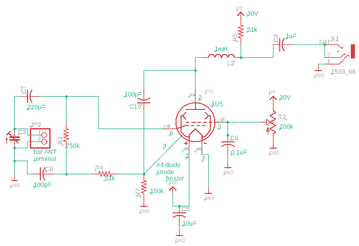
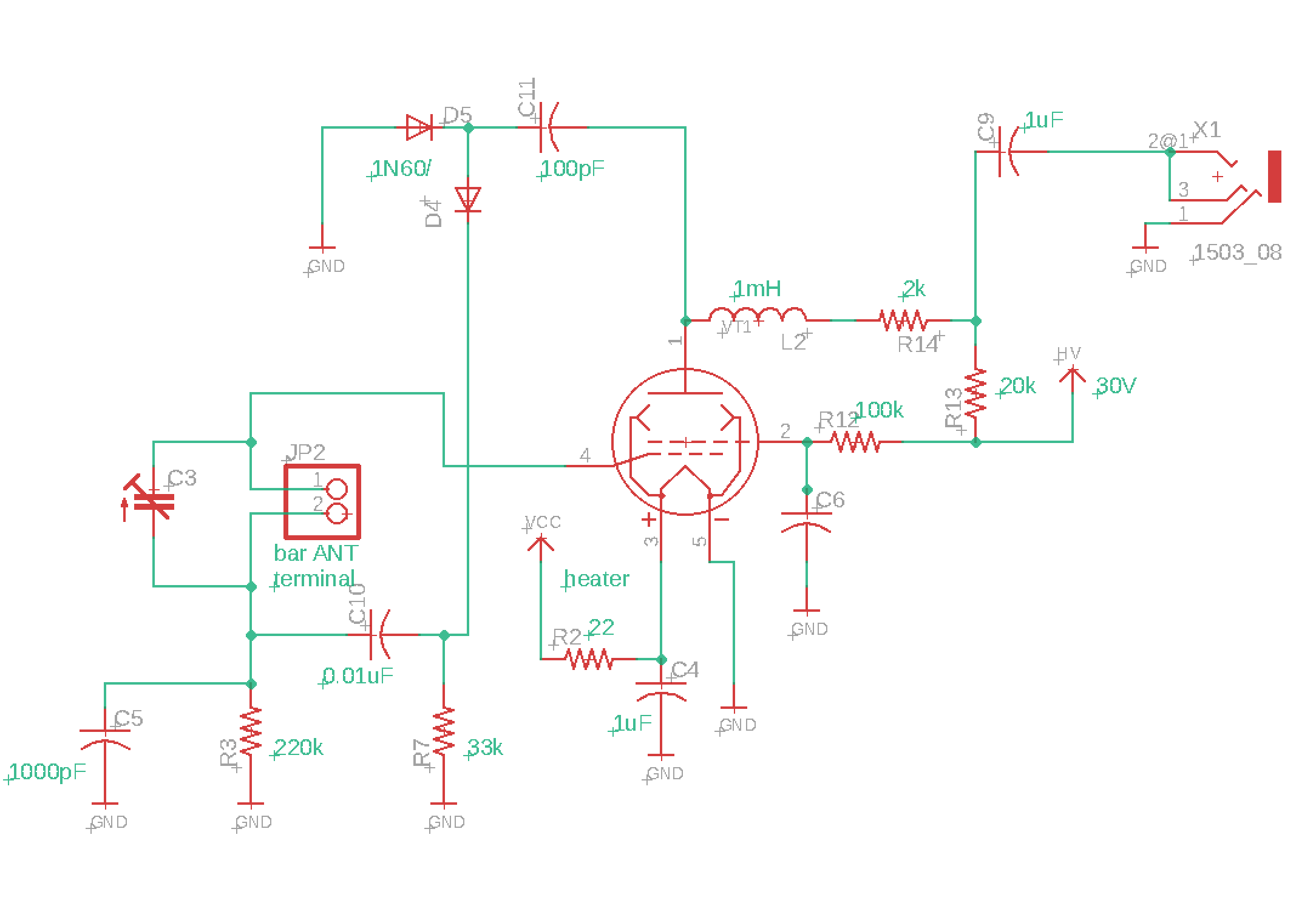
![]()
Here is the schematic of "diode-pentode" diode. It is also "reflex radio" where the rectified signal has a feedback through R4 and audio signal goes again to resonator.
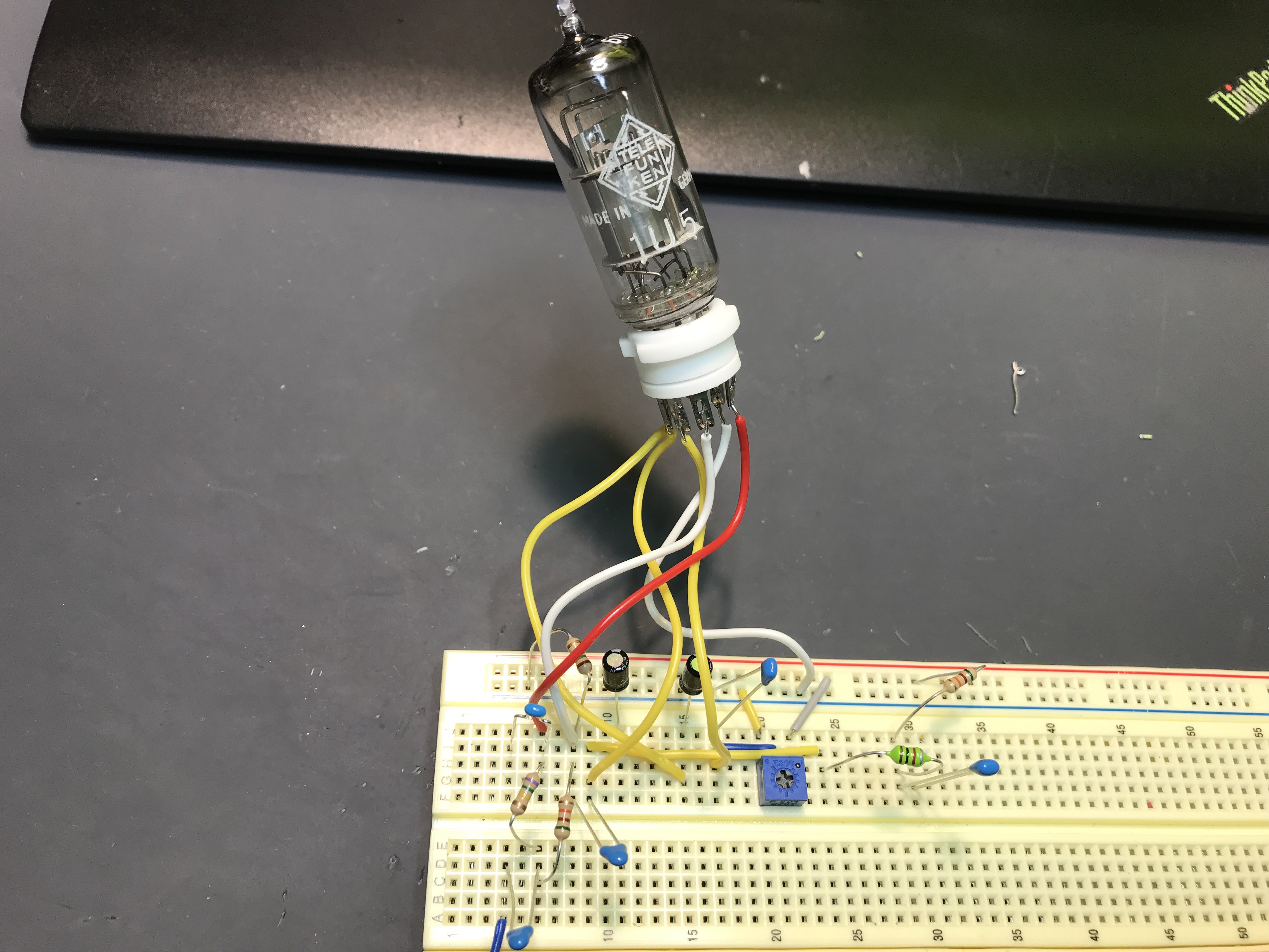
![]()
And this is the whole circuit except for resonator (VC and bar antenna). As you can see no "semiconductor diode". Actual operation can be found in the following movie! Yeah, it's working!
-
Printable retro radio enclosure
06/01/2019 at 13:06 • 0 comments![]()
Just naked PCB is not so smart. I made "printable" retro radio enclosure. The STL files are uploaded to hackaday file space and also my GitHub account. On the GitHub, you will see the preview of STL. The front panel cloth is, indeed, my wife's waste stocking socks. Please print if you need!
-
#3 Single subminiature vacuum tube radio
05/31/2019 at 12:25 • 0 commentsVacuum tube was made till around mid-80's even in US. Mostly they are military application and no consumer product except for high-end audio did use tube in that era. This time I got a vacuum tube made in such the end of vacuum tube era. It is "subminiature tube". Quickly I wired the radio (single tube reflex) #3 and show how it works in the following movie. The schematic and parameter will be presented later on this page but I can show now its operation.
![]()
And this is the schematic. It is quite simple but relatively high sensitive. Here let's follow the signal from RF to AF. Initially ferrite bar antenna and C3 (variable capacitor) organizing resonator and tuned signal goes to grid 1 (#4), and amplified signal from plate (#1pin) will deliver signal to diode rectifier (initially it does not contain AF and L2 works as RF choke) and rectified RF signal turns to audio signal and again go to resonator (C3 and ferrite bar) and again goes grid 1(#4). The amplified AF and RF comes out from #1pin (plate) and now audio signal can go through RF choke and indeed again some of them go to grid 2 (#2pin) and amplified audio signal comes out from plate #1pin. Indeed, it has a two loop for grid1 and grid 2, and both of them are audio signal feedback loop. (not RF). So RF oscillation will not occur (but audio oscillation can, indeed).Most of pentode can be replaced with small modification for heater voltage and R13 and R7.
-
#2, reflex radio by single vacuum tube
05/31/2019 at 07:39 • 0 commentsRegenerative and super-regenerative receiver are well-known circuits to build "simple but high sensitivity radio". These two words are similar but different in the principle. "regenerative" is simply build by "full positive feedback loop" to get high gain, and very easy to oscillate for strong signal input. (feedback value should be adjusted for each reception.) Indeed, it was super popular just after WWII in Japan, but GHQ prohibited to sell due to too much spurious emission in EM environment (I guess it jammed communication..)
Super-regenerative is periodically oscillating oscillator, which pulse width is modulated by input signal. Indeed, it can work not only low frequency but up to GHz range, including second harmonics (very close to injection locking) but it has a issue of noise emission.
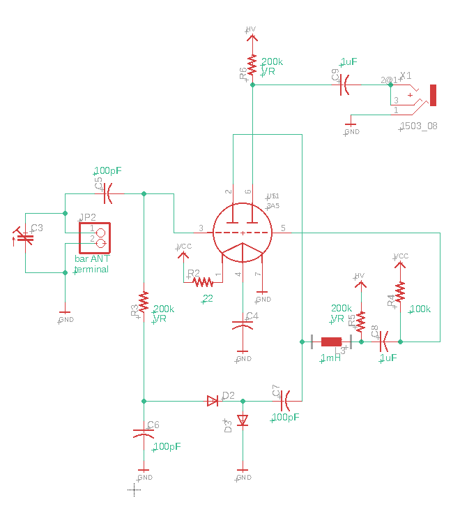
The circuit of "reflex" is different from regenerative nor super-regenerative.
![]()
Here is one example circuit can be made in breadboard. You may find similarity with #1 straight radio, but sooner you will find one strange point. D2, and D3 consisting rectifier, but the output goes back to the grid (#3)??
This is the way to operate. C3, and ferrite bar antenna in JP2 consists resonator, and goes to one of twin triode, grid (#3). The amplified RF signal goes to C7 and entering D2 and D3 and they produce audio signal. The shunt capacitor and R3 will work as LPF and the audio signal goes gain to #3. YES, it is feedback look. The difference between regenerative and reflex are, regenerative will feedback everything including RF and AF, but in the case of reflex, only AF signal has a feedback look (therefore, no fear of RF signal oscillation and emission.) Again the amplified AF (and RF) signal goes to grid #3 and amplified again and goes to L3. L3 is RFC and only AF signal goes through, and the filtered AF signal goes to second grid (#5) and amplified and goes out to earphone terminal. Yeah, it works as like this.
Indeed, I've completed the preparation as kit form and started to sell at my tindie store. But of course you can find parts by yourself and easily make this radio circuit. Compared with #1 radio, reflex has more good sensitivity and if you can find proper impedance transformer, you may be able to drive speaker just by single tube! Please try!
Vacuum tube game in 21st century
Playing vacuum tube is not so difficult as expected. Let's play great heritage of human being by modern technology!