Close
0%
0%

DXF Laser/Mill Box Maker

A Linux program to create a DXF file (for QCAD) for a laser cutter or CNC mill.

Similar projects worth following
The program is a port of a DeltaCAD macro I wrote to create laser cut boxes.
I have ported the code to C, used "xForms" for the dialog, the "ezx" graphics display library and a simple "dxfout" library I wrote.
My dxfout library uses the very old dxf format that may not be supported by all CAD packages.
It works with QCAD or LIbreCAD very well.

Box Maker

Box Maker is a simple but long program that creates a box for a Laser Cutter or a CNC Mill.

Here is an example:
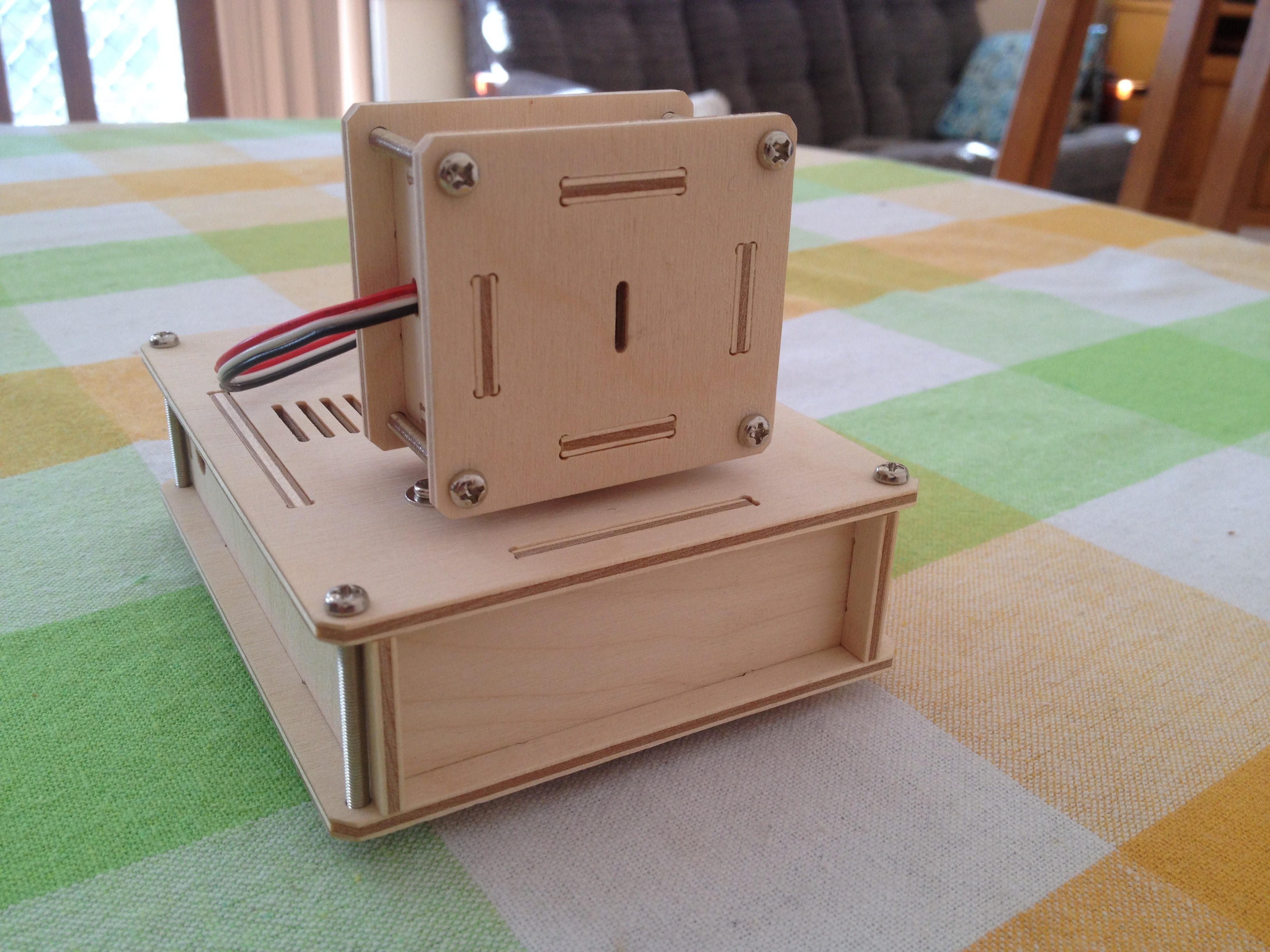
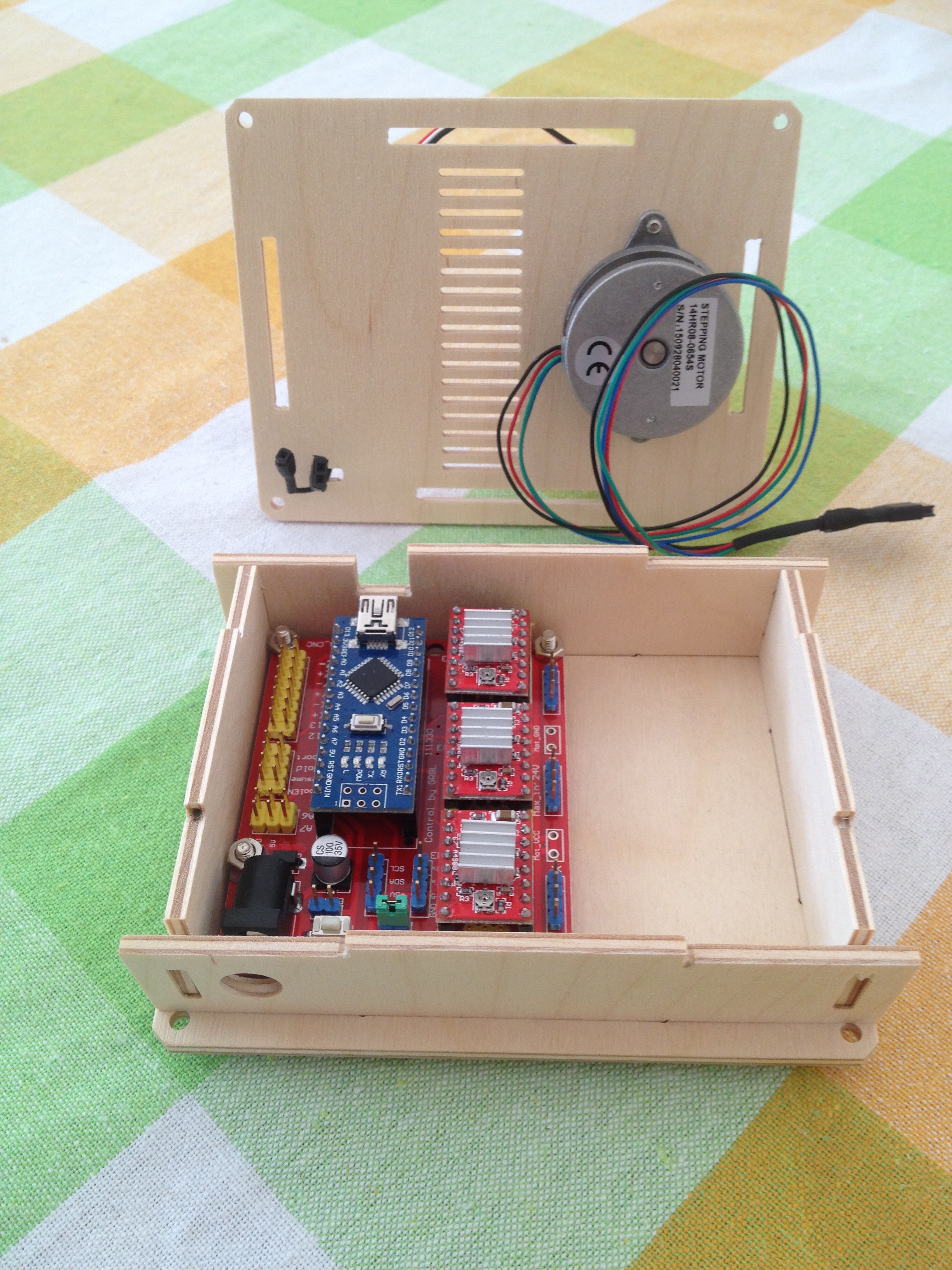
What is inside the boxes?
And:
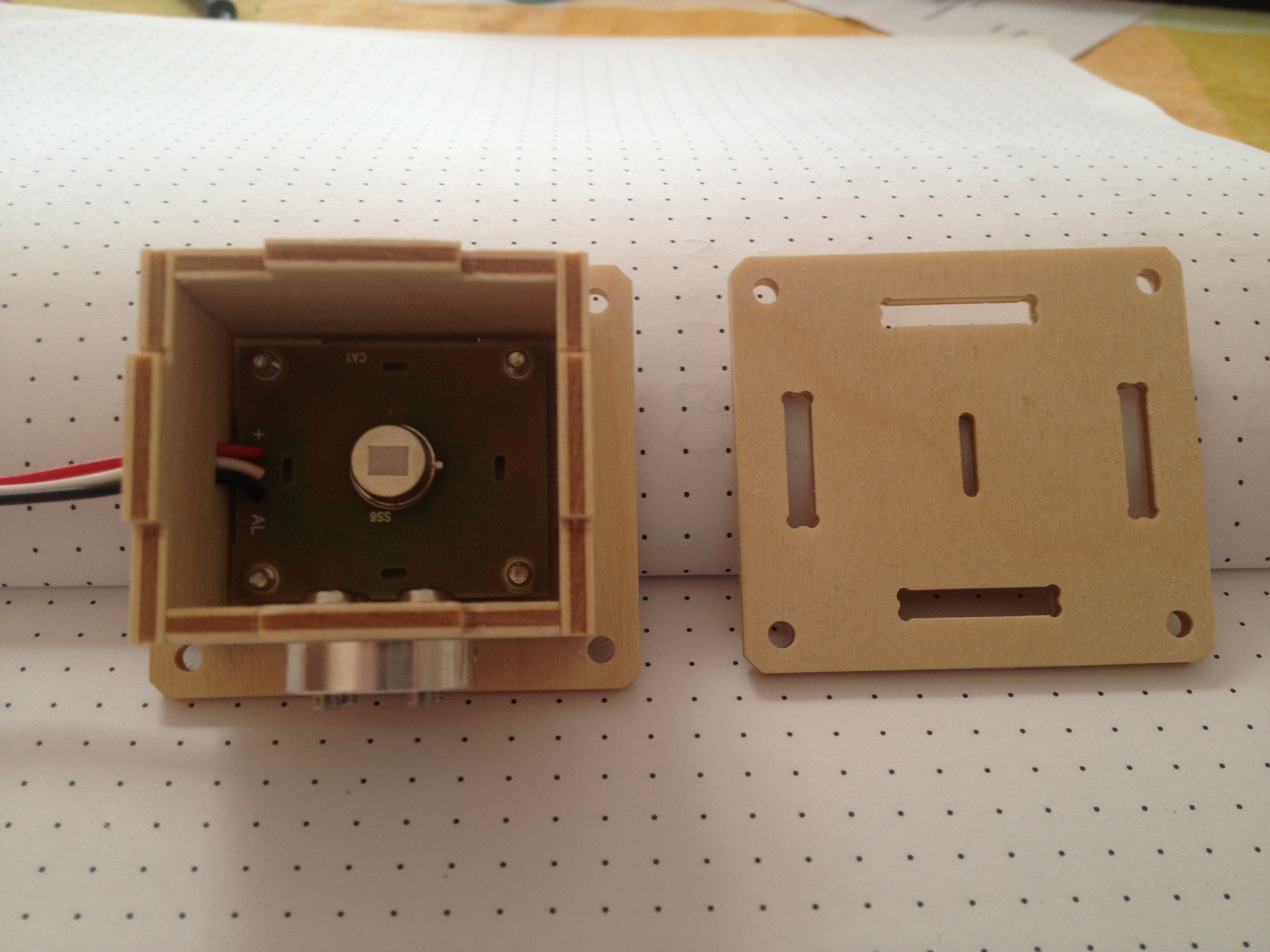
You will notice that the boxes were cut with a CNC mill thus the inside corners are "dog boned", that is drilled out. Here is the "box maker design" that I used at the time:
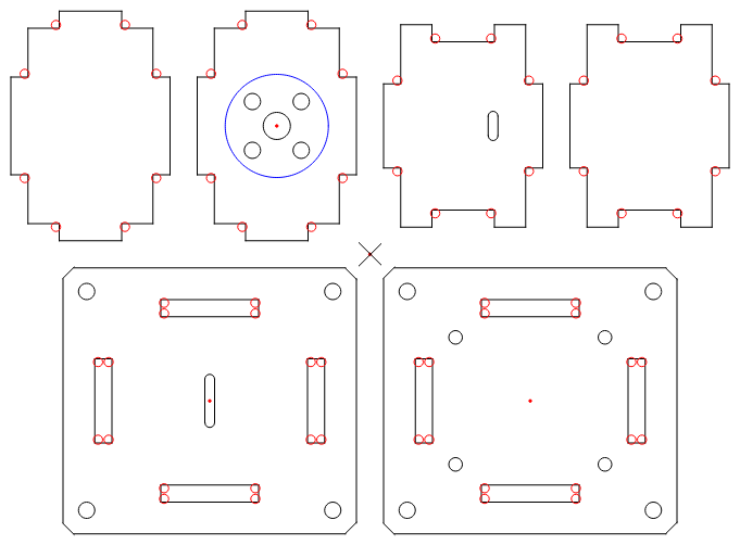
DLGDSN

The dialog form designer that DeltaCAD macro uses is "dlgdsn". It does not appear to be available for C:
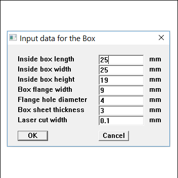
So I have used xForms instead. Now I have looked at other GUI libraries but xForms has documentation, worked examples, a form designer and is not hard to compile (i.e. not too many dependencies).

Linking xForms is easy too:

  • -lforms -lX11 -lm

But this is for a shared library.

I have realised that to share the program I have to use the static library and compile with:

  • -l:libforms.a -lX11 -lm

Why? Because it is very likely and user will not have xForms installed on there system.

So here is the xForms dialog for Box Maker:
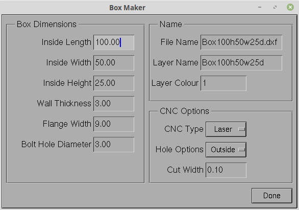
fdesign

"fdesign" is the form designer for xForms. After laying out and setting the widget types, the form designer exports the "main", the "form", the "callbacks" and the "header" files. This can be compiled for a "look and feel".

In theory you just edit the code for the final product. That did not work for me as I did not understand the structures used that well. In the end I used the "choice" example as a based and built up that code using bits and pieces produced by the form designer.

I am not really trying to build a GUI program but a console program with a GUI dialog box.

Options

As you may have noticed, the dialog has a number of options. Some to suit a laser cutter and others to suit a CNC mill. The "Cut Width' is used both for the laser beam cut width and for the CNC mill bit width, depending on the "CNC Type" selected.

Typically the lase beam width (i.e kerf) varies between 0.1 mm to 0.3 mm.

The "Hole Options" refers to the bolt hole locations. They can be on the inside of the box, one the outside (i.e. in the flange) or none.

AlanX

Mill100h50w25d_HeightPartition.dxf

AutoCAD DXF - 122.35 kB - 06/07/2019 at 01:23

Download

Box100h50w25d.dxf

AutoCAD DXF - 8.76 kB - 06/07/2019 at 01:23

Download

rBoxMaker.run

- 462.55 kB - 06/05/2019 at 09:26

Download

rBoxMaker.c

text/x-csrc - 38.72 kB - 06/05/2019 at 09:26

Download

xforms.pdf

Adobe Portable Document Format - 2.14 MB - 05/31/2019 at 13:17

Preview

View all 12 files

  • Using Divide and Conquer

    agp.cooper06/02/2019 at 10:27 2 comments

    Using Divide and Conquer

    Instead of a single hard coded procedure, use some intelligent sub-routines (i.e. procedures).

    What am I talking about? My BoxMaker code terrible. It is 800 lines long, hard coded and took forever to write and test.

    Intelligent code would be code that progressively breaks the problem down into sub-problems. Sub-problems are always easy to code and debug.

    Okay, here is the new and very short "makeBox" procedure (not yet fully featured but a start):

    static void makeBox(FILE *F1,char *LayerName,int LayerColour,double Length,double Width,double Height,double XOffset,double YOffset,bool Direction,double Tab,double Flange)
    {
      makeSquare(F1,LayerName,LayerColour,XOffset               ,YOffset         , Width,Length,Direction,-Tab,-Tab,Flange); // Top  #1 - Slot/Slot
      makeSquare(F1,LayerName,LayerColour,3*XOffset+Width       ,YOffset         ,Height,Length,Direction, Tab,-Tab,   0.0); // Side #1 - Slot/Tab
      makeSquare(F1,LayerName,LayerColour,5*XOffset+Width+Height,YOffset         ,Height, Width,Direction, Tab, Tab,   0.0); // End  #1 - Tab/Tab
      makeSquare(F1,LayerName,LayerColour,XOffset               ,YOffset*3+Length, Width,Length,Direction,-Tab,-Tab,Flange); // Top  #2 - Slot/Slot
      makeSquare(F1,LayerName,LayerColour,3*XOffset+Width       ,YOffset*3+Length,Height,Length,Direction, Tab,-Tab,   0.0); // Side #2 - Slot/Tab
      makeSquare(F1,LayerName,LayerColour,5*XOffset+Width+Height,YOffset*3+Length,Height, Width,Direction, Tab, Tab,   0.0); // End  #2 - Tab/Tab
    }

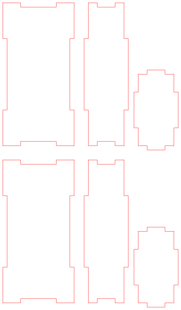
    So what does it do? It creates six squares that represent the sides of the box, like this:

    But to create those squares it has to call a "makeSquare" procedure:

    static void makeSquare(FILE *F1,char *LayerName,int LayerColour,double XStart,double YStart,double Width,double Height,bool Direction,double TabX,double TabY,double Flange)
    {
      DXF_PolylineBegin(F1,LayerName,LayerColour);
      if (Direction) { // Clockwise
        makeLine(F1,LayerColour,XStart      ,YStart       ,XStart      ,YStart+Height,Direction,TabX,Flange);
        makeLine(F1,LayerColour,XStart      ,YStart+Height,XStart+Width,YStart+Height,Direction,TabY,Flange);
        makeLine(F1,LayerColour,XStart+Width,YStart+Height,XStart+Width,YStart       ,Direction,TabX,Flange);
        makeLine(F1,LayerColour,XStart+Width,YStart       ,XStart      ,YStart       ,Direction,TabY,Flange);
      } else {         // Anti-clockwise
        makeLine(F1,LayerColour,XStart      ,YStart       ,XStart+Width,YStart       ,Direction,TabY,Flange);
        makeLine(F1,LayerColour,XStart+Width,YStart       ,XStart+Width,YStart+Height,Direction,TabX,Flange);
        makeLine(F1,LayerColour,XStart+Width,YStart+Height,XStart      ,YStart+Height,Direction,TabY,Flange);
        makeLine(F1,LayerColour,XStart      ,YStart+Height,XStart      ,YStart       ,Direction,TabX,Flange);
      }
      DXF_PolylineEnd(F1);
    }

    And makeSquare calls makeLine, that makes lines with "tabs", like this:

    You may have noticed TabX and TabY options in the code. This allow me to swap the tab direction as in the case of the second (or middle) square (above).

    The "makeLine" code is a little more complicated:

    static void makeLine(FILE *F1,int LayerColour,double xstart,double ystart,double xend,double yend,bool Direction,double Tab,double Flange)
    {
      double dl,dx,dy,x1,y1,x2,y2;
      ezx_color_t Clr=GetClr(LayerColour);
    
      dx=xend-xstart;
      dy=yend-ystart;
      dl=sqrt(dx*dx+dy*dy);
    
      if ((Flange<=0.0)||(Tab>0.0)) {
        // No Flange Case
        x1=xstart;
        y1=ystart;
        x2=xstart+dx/4;
        y2=ystart+dy/4;
        ezx_line_2d(disp,(int)(scale*x1),height-(int)(scale*y1),(int)(scale*x2),height-(int)(scale*y2),&Clr,1);
        DXF_PolylinePoint(F1,x1,y1,0.0);
        DXF_PolylinePoint(F1,x2,y2,0.0);
    
        x1=x2;
        y1=y2;
        if (Direction) {
          x2=x1-Tab*dy/dl;
          y2=y1+Tab*dx/dl;
        } else {
          x2=x1+Tab*dy/dl;
          y2=y1-Tab*dx/dl;
        }
        ezx_line_2d(disp,(int)(scale*x1),height-(int)(scale*y1),(int)(scale*x2),height-(int)(scale*y2),&Clr,1);
        DXF_PolylinePoint(F1,x2,y2,0.0);
    
        x1=x2;
        y1=y2;
        x2=x1+dx/4;
        y2=y1+dy/4;
        ezx_line_2d(disp,(int)(scale*x1),height-(...
    Read more »

View project log

Enjoy this project?

Share

Discussions

Similar Projects

Does this project spark your interest?

Become a member to follow this project and never miss any updates