Sander van de Bor
-
Preparing Arduino IDE to write sketches for the ATtiny 0- and 1-series
06/04/2019 at 01:36 • 1 commentArduino is a great tool for makers and hobbyists to develop code for tons of different micro-controllers. For the user the code always looks very similar and most code can be compiled for different devices. But in order to make this all happen a lot is happening behind the scenes of Arduino, and a lot of different parties are involved.
Different “translations” are done from the sketch in Arduino to the actual machine code which will be uploaded to the micro-controller. The language the micro-controller is speaking differs for each controller and must be provided by the manufacturer. In this case the ATtiny 0- and 1-series are provided by Microchip and Microchip provides the language in a so-called Device Family Pack (DFP).
When you compile a sketch in Arduino with verbose output turned on (in settings) you will get the location of the compiler and the DFP in the Arduino IDE output window. For example, when you compile a sketch for the Arduino UNO you might see lines like:
C:\Users\username\AppData\Local\Arduino15\packages\arduino\tools\avr-gcc\5.4.0-atmel3.6.1-arduino2\lib\gcc\avr\5.4.0
When you browse to that folder it will show all the different devices that are similar to the micro-controller used on the Arduino UNO (ATMEGA328P), with a complete list shown in the folder device-specs. The files in the device-specs folder are loaded, specific for the micro-controller, to tell the compiler where to find libraries for this device.
Some might notice that the ATtiny1616 is part of the list. Adding the ATtiny 0- and 1-series DFP to Arduino was requested a couple of months ago and they were so kind to make it standard in the latest releases. But just updating the DFP with new packages will not always do the trick. Sometimes new functions are added, and these must be understood by the translator, in this case the compiler.
Arduino is using avr-gcc compiler for the 8-bit microcontrollers. Version 5.4.0 was sufficient for micro-controllers like the ATMEGA328P and the ATtiny series like the ATtiny85 and ATtiny84a. Unfortunately, this compiler version had issues with the new DFP for the 0- and 1-series and a newer compiler version is required (and available).
While the DFP is provided by the manufacturer of the chip, the actual Arduino Core is developed by the Arduino team. It is a collection of libraries which are used to translate the language spoken in Arduino to commands or write to registers described in the DFP. For example, we are all familiar with the delay function. On the Arduino UNO the following function is used (all in the background, so you probably did not even know you were calling out functions):
void delay(unsigned long ms)
{
    uint32_t start = micros();

    while (ms > 0) {
        yield();
        while ( ms > 0 && (micros() - start) >= 1000) {
            ms--;
            start += 1000;
        }
    }
}
Unfortunately, this will not work for the new ATtiny 0- and 1-series, a new core is required.
Luckily enough the Arduino team did come out with a new core and compiler when they released the Arduino UNO WIFI REV2. This new device is using the ATMEGA4809, part of the megaAVR 0-Series, and in the same family as the ATtiny 0- and 1-series. You can see the changes by adding the board from the board manager and just compile an empty sketch with the Arduino Uno WiFi Rev2 board selected. You will notice that the avr-gcc version 7.3.0 is used. The Arduino core is different too, for example the function for delay is now as follows:
void delay(unsigned long ms)
{
    uint32_t start_time = micros(), delay_time = 1000*ms;

    /* Calculate future time to return */
    uint32_t return_time = start_time + delay_time;

    /* If return time overflows */
    if(return_time < delay_time){
        /* Wait until micros overflows */
        while(micros() > return_time);
    }

    /* Wait until return time */
    while(micros() < return_time);
}
With the Arduino core, compiler and DFP in place it should be pretty straight forward to make a variant for the ATtiny series.
Next log will be on creating board variants files.
-
DIP version of ATtiny1616
06/02/2019 at 18:30 • 7 commentsSMD components are getting more popular. They are easy to assemble in production and they get small, very small! Unfortunately with the rise of SMD the through hole version, the Dual In-line Package (DIP), is no longer available for newer micro-controllers and break-out boards are needed to use these on the breadboard.
The ATtiny1616 is available in two packages, the 20-Pin SOIC and the 20-Pin VQFN. For the 20-Pin SOIC there are some break-out boards widely available, for example: https://www.adafruit.com/product/1206
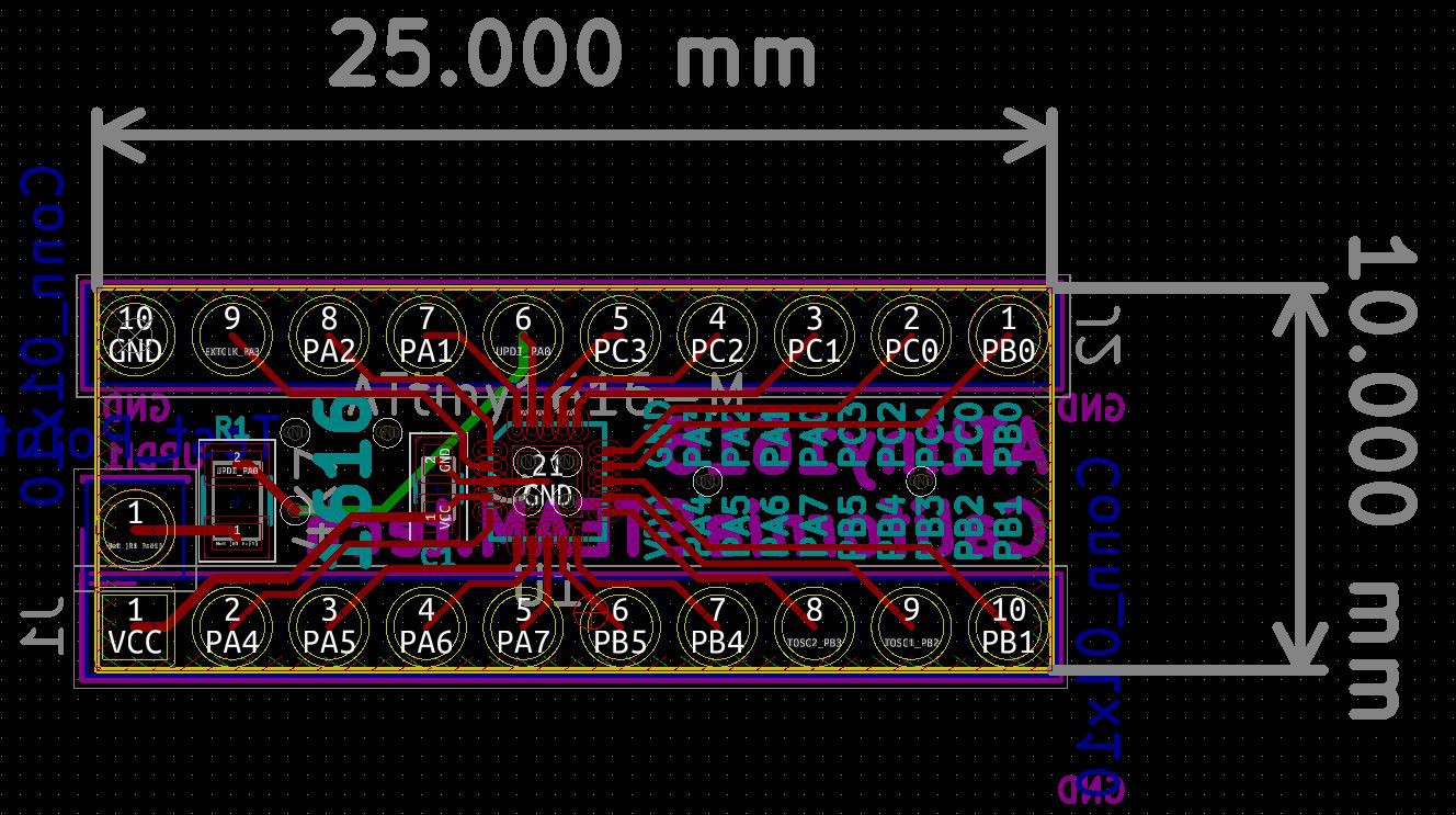
While the SOIC works great, it is relatively large. Instead, the VQFN version is only 3x3MM and allows some additional features which can be added to a custom break-out board for the ATtiny1616.
Since this micro-controller has a build in 20MHz oscillator and will run between 1.8V to 5.5V, there is no need for almost any additional components. A bypass capacitor is recommended between GND and VCC for the microelectronic and a 4.7K Ohm resistor from the programmer to the UPDI pin. The actual pin out position will match the SOIC and see here the results:
![]()
Schematic is available in the files section of this project.
Next step is preparing the Arduino IDE to compile sketches.
-
Uploading sketches to the ATtiny1616
06/02/2019 at 04:35 • 0 commentsThe ATtiny micron-controllers are very popular in the makers community. Only a single capacitor is recommended to stabilize the incoming power and different power sources between 1.8V to 5.5V can be used. The 8MHz internal oscillator will work for most projects and at a cost of about $1 for the DIP version it can be integrated into a project for a fraction of a full blown Arduino UNO.
In order to program micro-controllers programmers are used and offered by the manufactures from these chips. The cost of these programmers start around $50 and can go up to a couple hundreds of dollars. While these programmers are great, and excellent for debugging as well, it is a cost that most makers are not willing to spend. Fortunately the Arduino platform offered a solution where the Arduino UNO can be programmed with a sketch to operate as an SPI programmer. Using the MOSI, MISO, SCK and reset lines allowed uploading sketches through the Arduino UNO to the ATtiny-AVR.
The new ATtiny1616 is a little bit different, and the SPI programmer for the ATtiny-AVR will no longer work. These so called tinyAVR® 1-Series, and similar to the tinyAVR® 0-Series and the megaAVR® 0-series, are using the UPDI 1-wire interface. This new protocol sound very promising since it only requires 1 pin to communicate instead of the 4 pins for SPI and fortunately an Arduino is already there!
El Tangas created a great solution (which can be used on the Arduino UNO) to turn most common Arduino devices into UPDI programmers. The code can be found on Github;
https://github.com/ElTangas/jtag2updi
While a like using the Arduino UNO (I have done all my ATtiny84a projects with the UNO) it is often bulky and requires a lot of wires. An alternative solution is upgrading a AVR JTAG ICE clone with new firmware per following instructions:
https://github.com/ElTangas/jtag2updi/tree/master/tools/avrjtagicev2
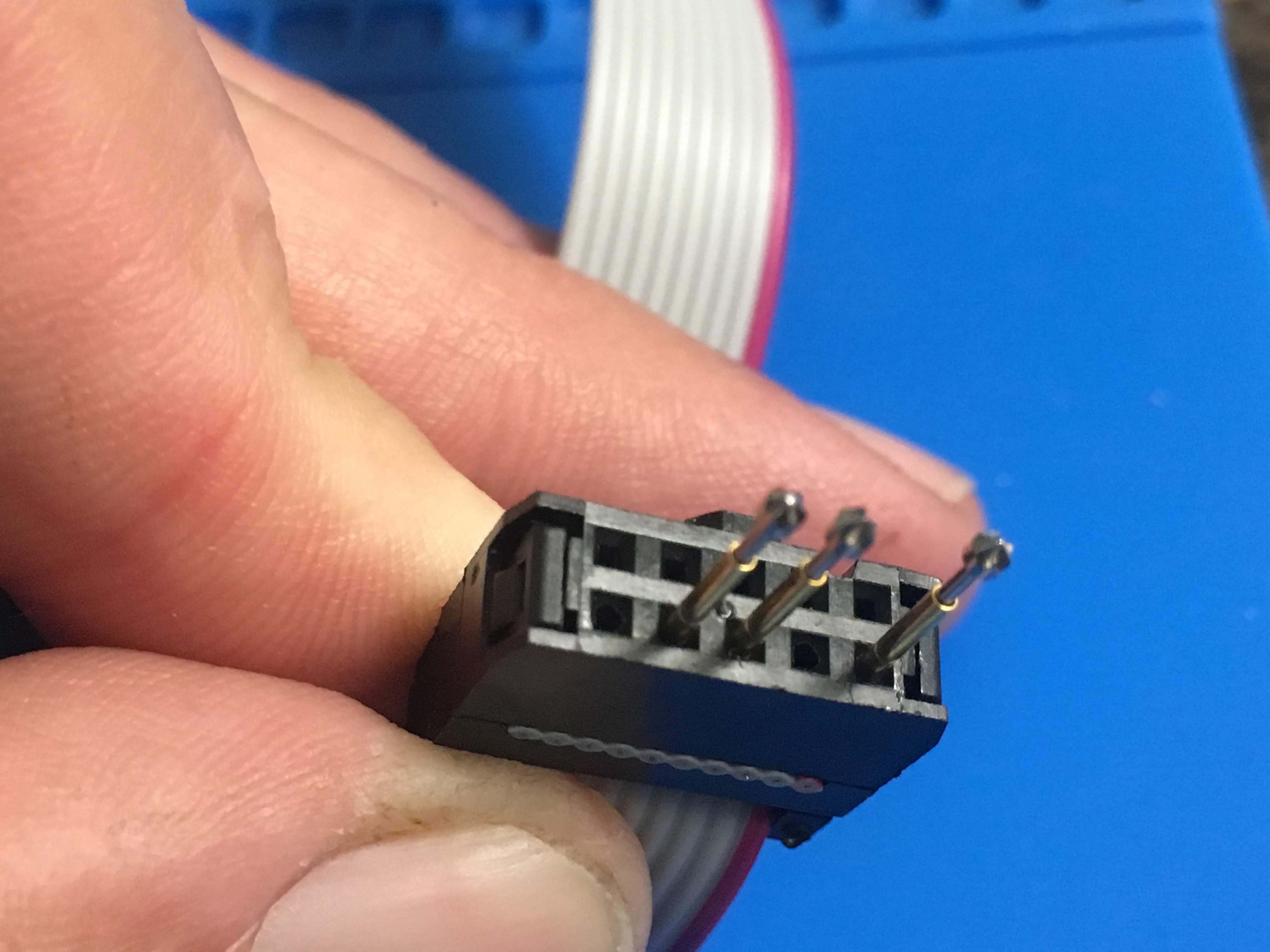
The 10 pin ribbon cable is great, because you can press 1.02 diameter pogo pins into the end.
![]()
It is very similar to the SEGGER pin needle adapters used for programming, but only at a fraction of the cost. While El Tangas shows connecting pin#2 to GND pin#4 for VCC and #6 for UPDI, I decided to use pin #10 for ground instead for the following reasons:
- The DIP break out board for the ATtiny1616 must fit on the bread board, and the VCC and GND need 4 pins spacing between each other, which I get by having VCC on pin #4 and GND on pin #10
- Having the 3 pins separated by an empty pin generates a key so that connecting it to the board will only fit one way (originally the 3 pins were next to each other, so VCC and GND could easily be swapped.
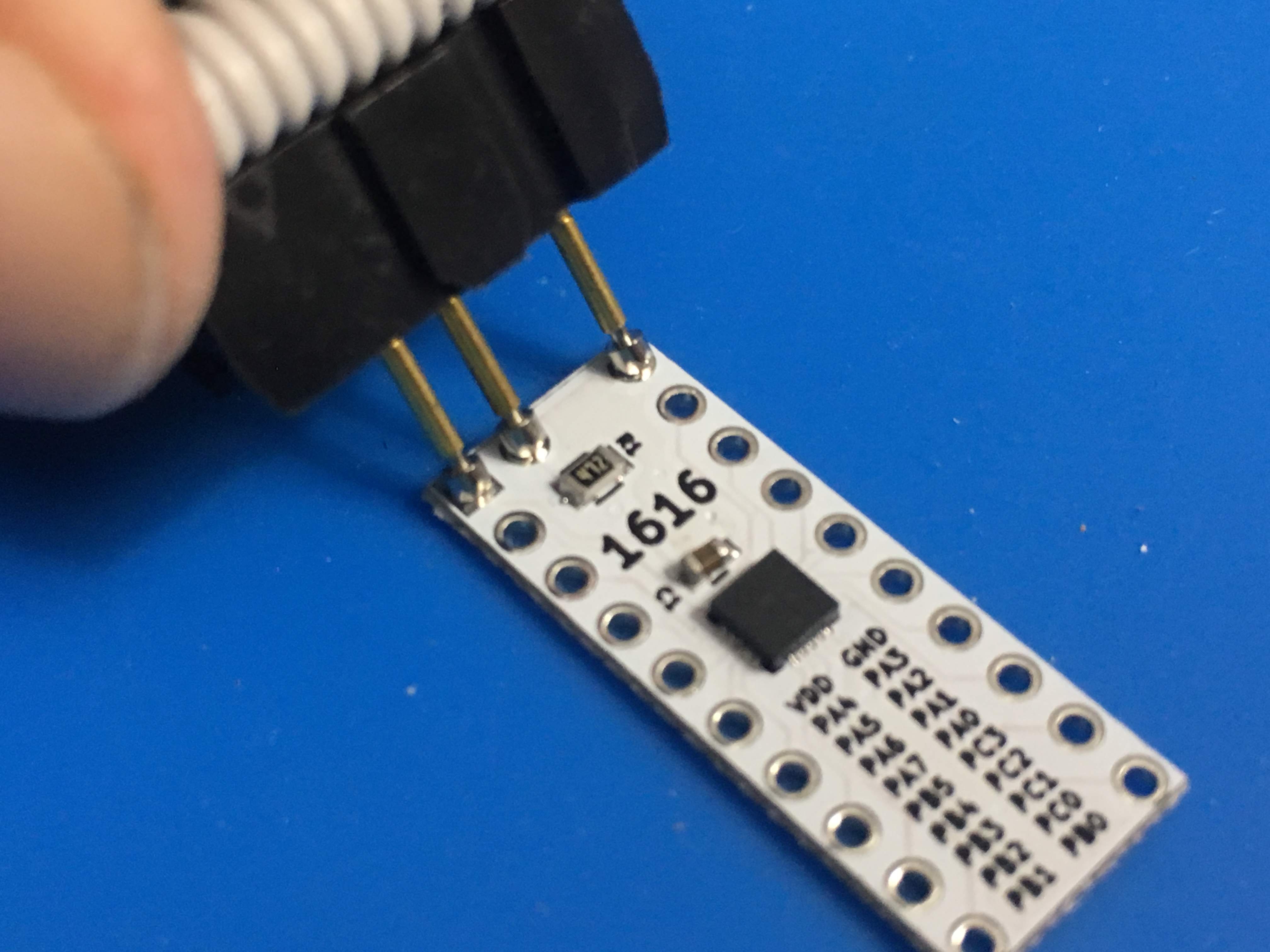
Here is a picture of how this is applied to the board:
![]()
With the pogo pins it is even possible to connect when header pins are applied:
![]()
Next will be the design of the break-out board.
ATtiny 1-series with Arduino support
Creating a break-out board for the ATtiny1616 where sketches can be uploaded from Arduino with the Arduino UNO or a modified AVR JTAG ICE