The PCB we make will control the current with 8 bits, use a PIC24F16KA controller, and a MCP7940 real time clock.
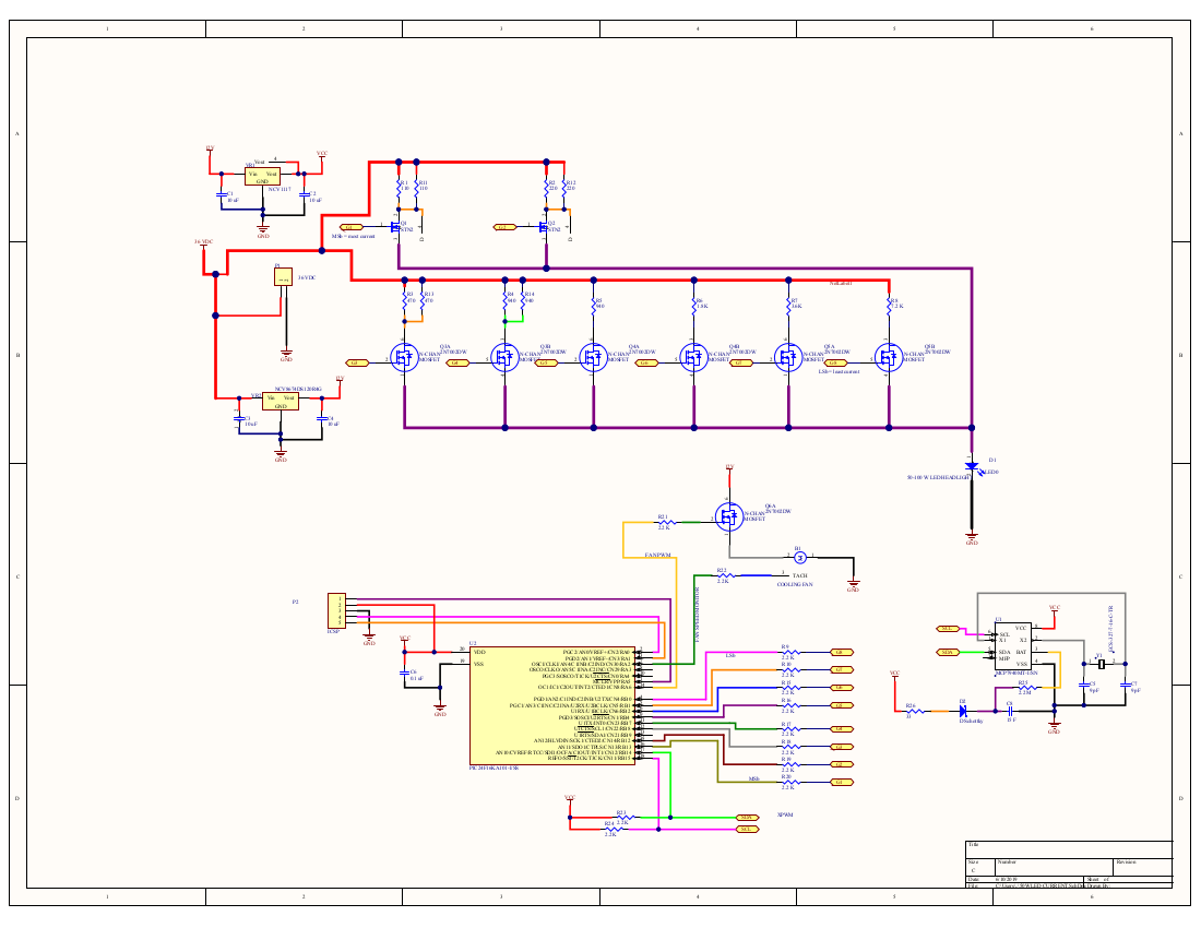
The PIC talks to the RTC over SDA & SCL lines using I2C. Power input (P1) comes from a 36VDC LED driver that plugs into 115 VAC. Voltage regulators down-shift the 36 V to 12V (for the cooling fan) and ultimately Vcc (which is 3.3 V). You see all eight current control MOSFETs, and there is a single mosfet controlling the fan speed.
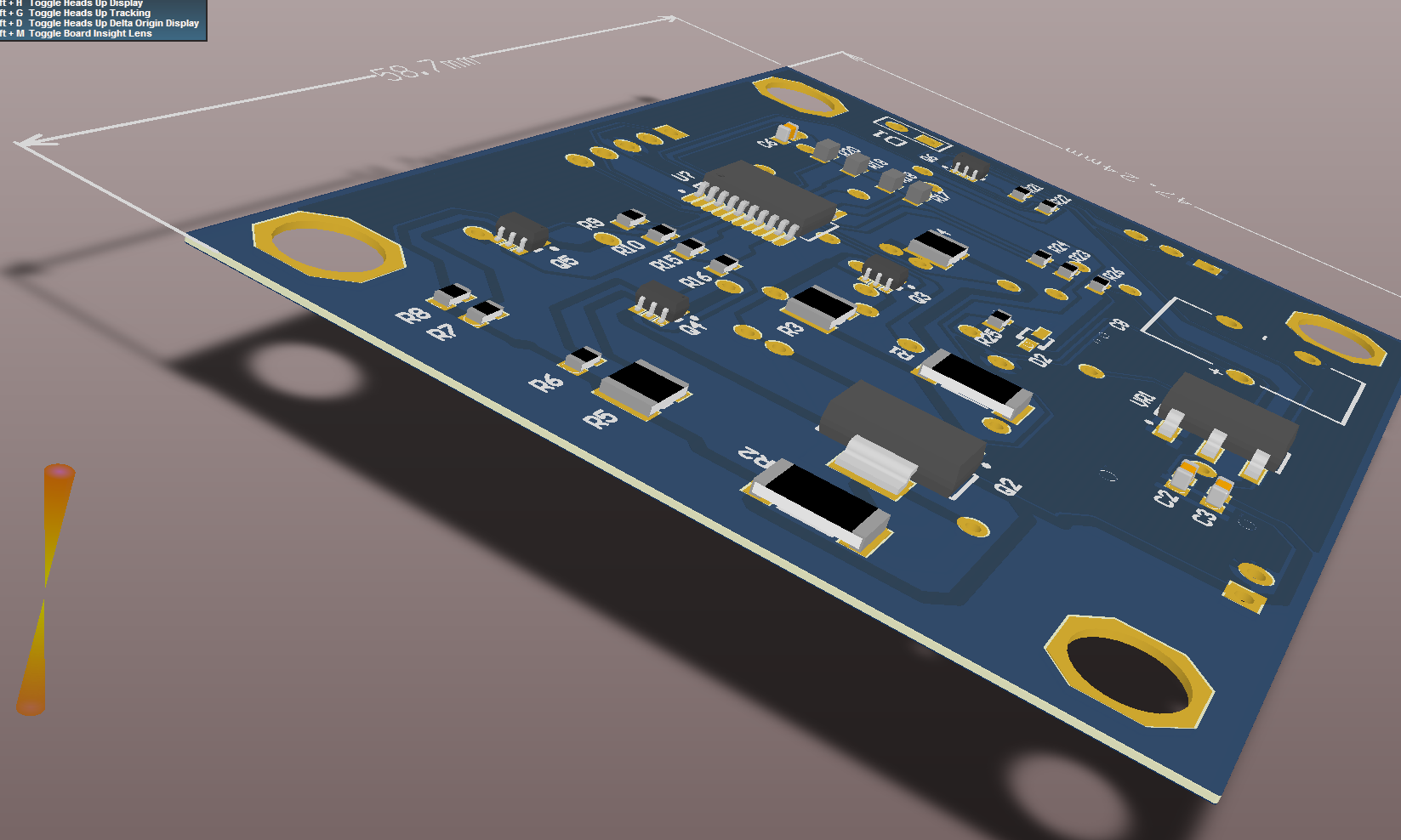
The diurnal curve previously shown is programed into the PIC's memory as a list of 8-bit integers (from 0 to 255 representing a normalized insolation of 0 - 1.0). The two-sided PCB is 59mm x 47mm.
A five-pin header is provided (P2) for programming the PIC.
This should be sufficient to prove that the concept works.
Next, I intend to add an I2C flash memory to the bus.
Then add control for a blue LED (for lunar).
Then, USB ...
Then, Bluetooth, so one board can control many.
Discussions
Become a Hackaday.io Member
Create an account to leave a comment. Already have an account? Log In.