 Alan Green
What I Bought
I bought the cheapest laser galvo mirror set that I could buy, that also had reasonable shipping. I ended up with this one.

The set comes with the twin galvanometers, mounted on a metal block, two driver boards and a power supply. It cost about 100AUD on eBay (listing). Several of the sets on sale also offer a "show card", which will run laser displays from an SD Card. I wanted to build the display logic myself, so I didn't buy a show card.
The specs from the listing are:
-Input voltage:15V
-Peak current: 1A
-Rated current:0.5A
-Operating temperature:0~50℃
-Rated scanning angle:± 20 °
-Maximum scanning angle: ± 30 °
-Drive plate size:76mm × 48mm × 26mm
-Wavelength:380nm-700nm
-Analog signal input impedance: 200K ± 1% Ω (differential input)
-Analog position input range: ± 5 V.
-Scanning speed:20Kpps
-Lens reflectivity:> 98% @ 45 ° incidence (coverage wavelength: 380nm-700nm)
Important to note here:
- They are rated for 20kpps (20,000 points per second) at 20°. Here is a description of how that test is supposed to have been done. Note that, at the rated speed, the produced pattern looks different to how it does at a lower speed. The galvo mirrors aren't magical after all - they take a finite amount of time to move into position.
- The galvanometers are rated as consume 1A 15V, peak. That's quite a bit. One can see why a driver board is required.
- Input impedance is high, which is good.
Given the amount of power consumed, I think it's probably a good idea to aim for smaller angles of defletion and slower scan rates.
Power Supply
The supply came with two 3 pin connectors pre-attached to the output screw terminals. I confirmed with the multimeter that FG is connected to the chassis, while N & L are not. The G terminal is not connected to FG or to N (or L!).

Label on the power supply says it supplies 1A at 15V, which nicely matches the peak current draw spec.

There's quite a difference between input power rating (0.5A@100V = 50W) and output rating(1.0A@15V + 0.5A @ 15V = 22.5W). I suppose this means that the supply gets hot.
This is all about what I expected.
Galvos and Mirrors
As noted above, the galvanometers are firmly aligned in a metal block. Under the block are screw holes which are obviously useful for securing the block.

Hmm... looking at the photo, that mirror seems a little dusty. I'll need to clean them. The galvanometer PCBs each have the galvanometer, the connector, and nothing else:
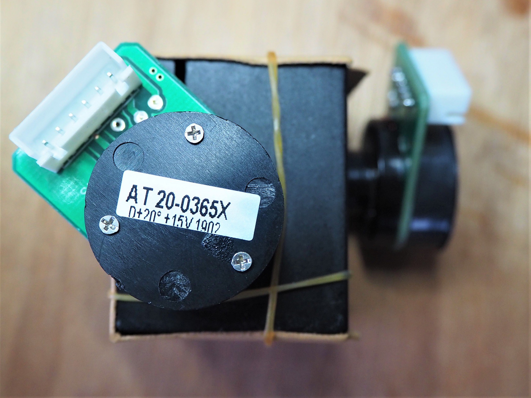
I'm not entirely sure why the connectors have 6 terminals each, but based on the cables, I'm guessing the galvos give some kind of feedback to the driver board.
Driver Boards
These boards are responsible for amplifying a high impedance, 10V differential signal into a low impedance 15V signal.
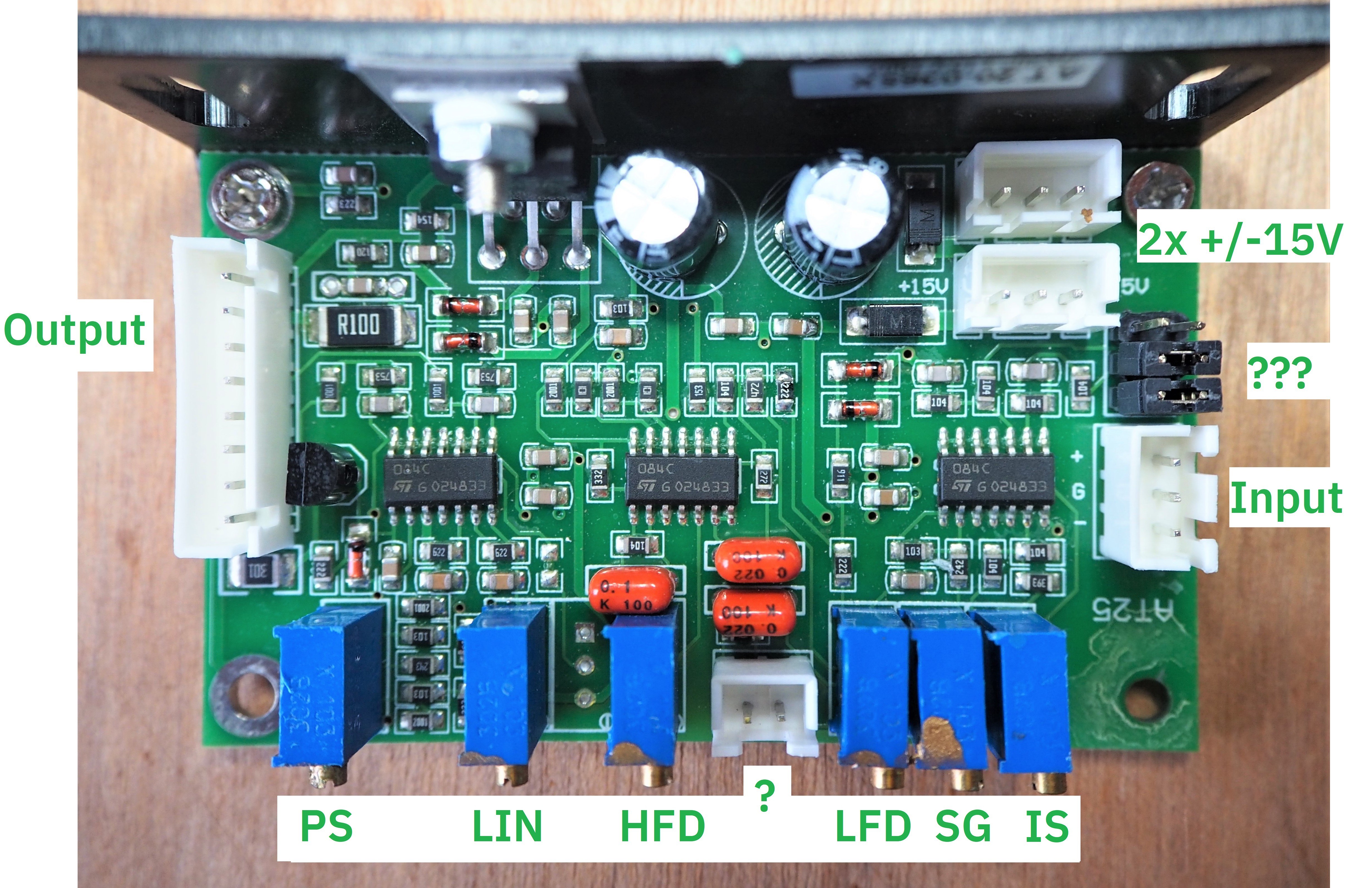
I've marked the connectors with their apparent function. There's signal input, two power connectors and an 8 pin output connector. The picture at the top of the page shows the cables that run between the 8 pin output connector on the driver board and the 6 pin connector on the galvo. The conductors run in two bundles.
Trimpots and Unknowns
The trimpots along the bottom each have two-letter markings on the underside of the board. I've put these markings in the picture. Based on this Aliexpress listing for a similar product, I'm guessing the meanings are:
- PS = Position Scale
- LIN = Zero Offset
- LFD = Low Frequency Gain
- HFD = High Frequency Gain
- SG = Servo Gain
- IS = Input Scale
All of them appear to be locked with a small amount of glue, except Input Scale. I won't touch any of them.
There is a 2x3 header area with two jumpers on it, next to the input. No idea what that is for.
Similarly, there's a 2 pin connector in between the trim pots that I have no idea about.
ICs
The 3 14-SOIC packages on the driver board appear to be TL084 Quad JFet Op Amps (datasheet), which cost about 0.20USD each, in quantity. They have a minimum rated output short circuit current of 10mA, which means they are not powerful enough to drive the galvos alone.
The back of the board has a vertical metal plate, which is used as a heat sink for a CD2030A audio amplifier IC (datasheet). It looks as though this amplifier was originally made by ST, and while it is now obsolete according to that manufacturer it is still being sold - and I am guessing still being manufactured - in China.
This amplifier is considered "pretty good for the price"... and the price is about 0.20AUD each.
The datasheet says it can provide 18W of power, and provide amplification up to 100kHz. This would appear to make it possibly suitable for driving galvos at 20kpps.
Discussions
Become a Hackaday.io Member
Create an account to leave a comment. Already have an account? Log In.