 Alan Green
I spent the past few days soldering up the PIC32 MCU and getting it to work with the Raspberry Pi.
It's Going To Work. Hooray! There were a couple of tweaks to the schematic, one dead PIC32, and a couple of moments of utter confusion with Microchip's MPLAB Harmony, but we're now in a good place.
Goals
I did this first since the PIC32 is an unknown for me - hence something that might go wrong. If it wasn't going to work, I needed to know early.
As a proof of concept, I had the PIC32 use a timer to blink an LED in a pattern. It also acted an SPI slave, ready to accept data from the RPi that it would use to change the LED blinking pattern.
Planning and Construction
 The picture to the right is a scan of my first planning sheet. While constructing it, I made a few changes, which you can see in the larger image, below.
One of the nice things about working on a Blueboard#01 is that one can almost always try a new configuration if something doesn't work. It also lends itself to constructing a circuit in stages.
The picture below is me getting excited about soldering up my first PIC32. Flux is on the footprint, and moving the chip into position.

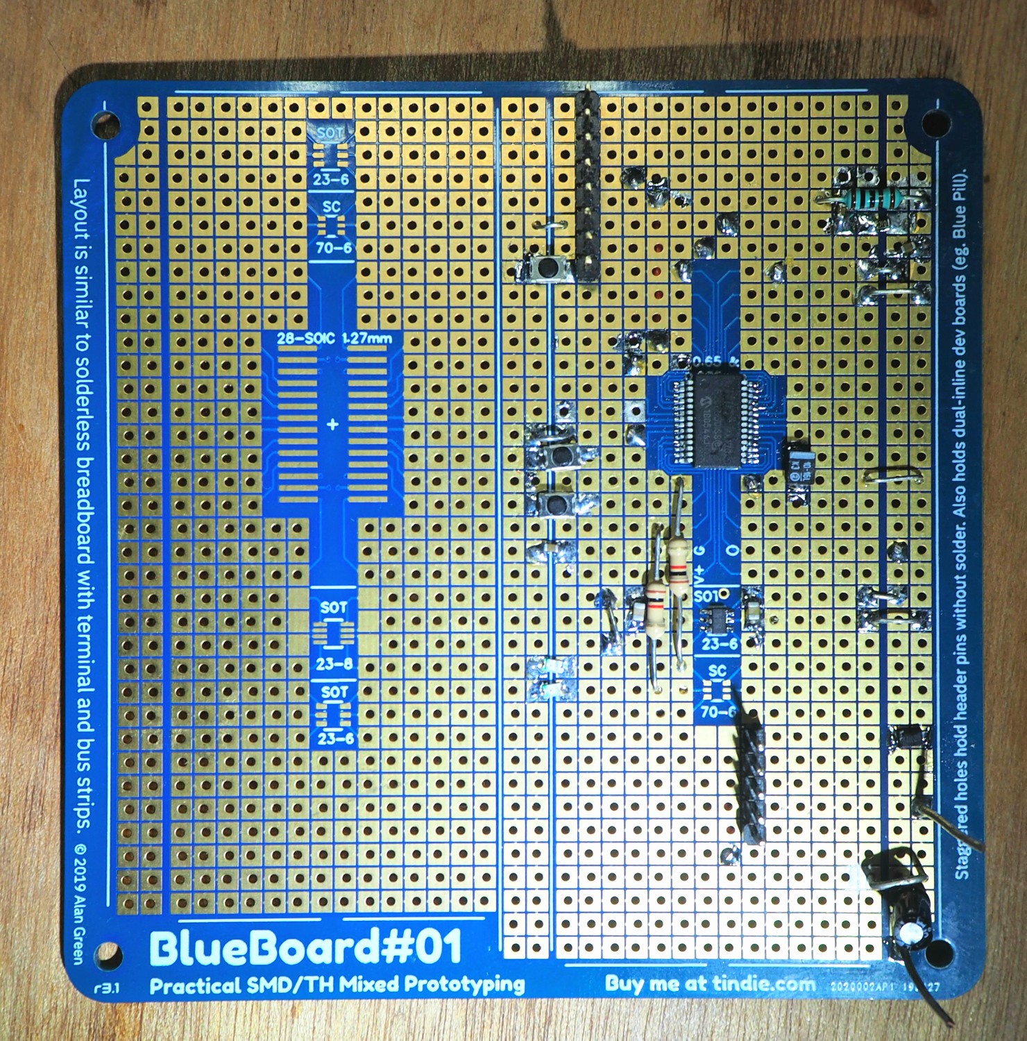
The end result was fairly neat, with only a few solder blots. Most of the wiring is hidden on the back of the board.
And the final planning sheet:

Software and Testing
The PIC32 sets up one timer peripheral and one SPI slave peripheral. It has a buffer containing a pattern.
- When the timer times out, it turns the LED on or off according to the pattern.
- When it receives data from the SPI peripheral, it updates the pattern.
I used the MPLAB Harmony framework, the MPLAB IDE and the the MPLAB Snap programming tool. Microchip should send me a T-shirt.
On the RPi side, I used Python and spidev. Spidev appears to be installed by default, which is great. It's pretty straight forward to send a bunch of bytes to an SPI slave.
Here it is, all together. The laptop has a window open to the RPi, the RPi is wired to the PIC on the Blueboard#01, and the Blueboard#01 is being probed by the oscilloscope.
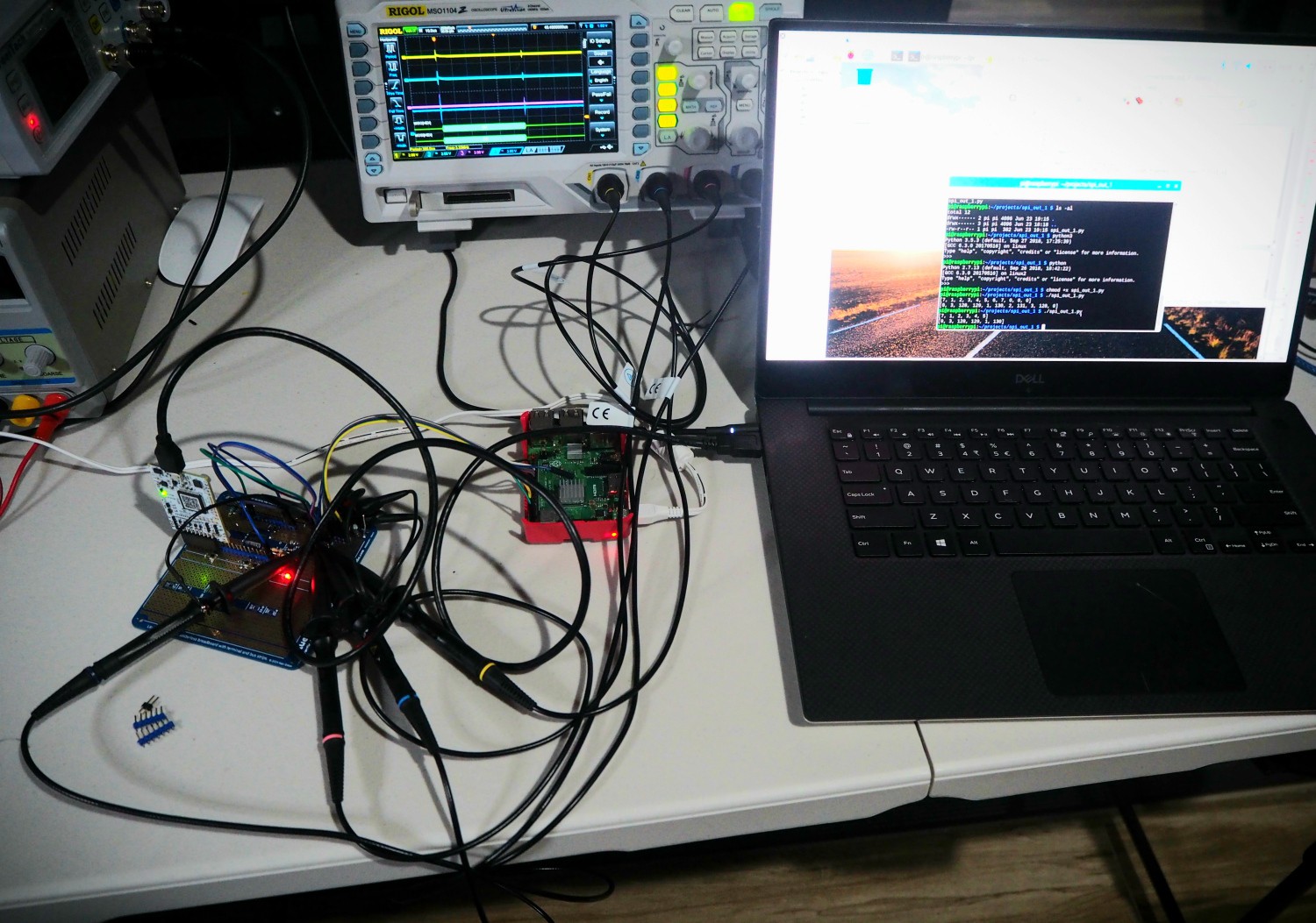
There are a lot of wires. I did this because the PIC32 is highly configurable, and I wanted to make sure I had the connections right, so I used 0.1" header pins pressed into the Blueboard#01, with dupont wires to make temporary connections. I'll solder in permanent connections, behind the board now that I know it works.
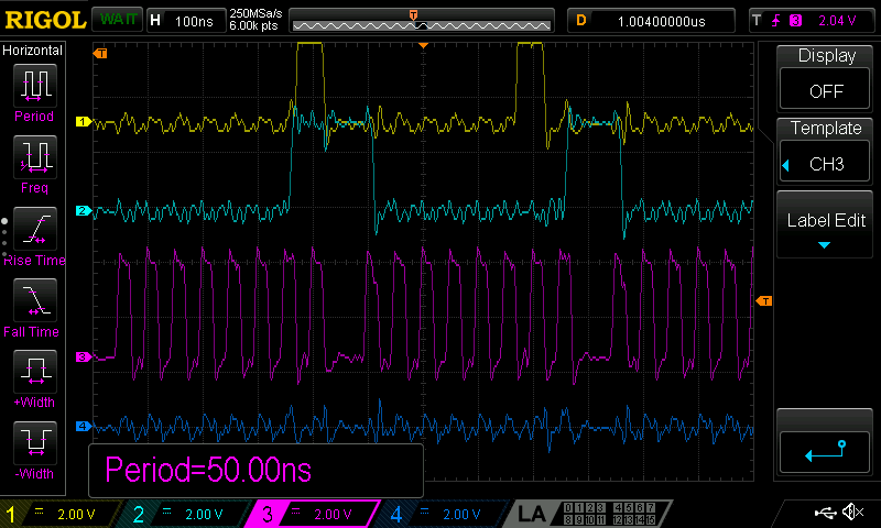
The oscilloscope is probing via a row of 0.1" header pins pushed into the Blueboard#01. With SPI running a 1 MHz clock, there were no problems at all. Channel 3 (magenta) is the clock:

It also works at 20MHz. This is suprising to me, given all the dupont wires going everywhere. At 20MHz, the waveforms are less well defined:
Lessons Learned
- Power is hard, as always: I had intended to power the MCU from the RPi's 3.3V supply. Not a great idea as it turns out. The RPi's 3.3V supply seems pretty marginal, and the PIC's 30mA seemed to bring it close to failure. I watched the voltage dip 0.1V as the MCU turned an LED on and off. Instead, I chose to power it from the 3V3Ref linear regulator. I may need a second linear regulator later if it turns out the PIC makes this one too noisy.
- Polarity is easy ... to get wrong. I blew up one PIC by connecting my bench power supply the wrong way around to GND and 3V3. They say that experience is what you get when you didn't get get what you wanted, and this was definitely an experience. The AVR chips I'm used to would have put up with that kind of abuse, but the PIC32 appears to be a different, more fragile class of device.
- MPLAB Harmony is complex. The PIC's default programming environment uses the MPLAB Harmony framework. It took me several days to wrap my head around it. I made peace with it for now - Most Things Just Work Once You Know How.
- Protocols require attention. The RPi/PIC32 SPI protocol was pretty simple in this proof-of-concept: the RPi sends a fixed number of bytes. For driving the laser galvo, there will be a variable number of bytes, and this will require careful thought to ensure the PIC understands packet boundaries. One would think the PIC could use the Slave Select pin to know where a packet starts and ends, but it turns out that the PIC doesn't work that way, at least not easily.
Next Steps
Next up, I'll solder up the DAC and op-amps.
Discussions
Become a Hackaday.io Member
Create an account to leave a comment. Already have an account? Log In.