 Alan Green
Progress! Here's a pattern generated by the PIC32, sent to the DAC, turned into twin differential signals by the op-amp and sent to the galvo:

It is a cross inside a square. However, I have not yet hooked up the FET to control the laser, so the laser doesn't turn off while moving between the ends of the cross and the bottom left of the square.
Apart from that, there are several noteworthy artifacts in this image:
- At three of the square corners, there is a spike where the mirror has - despite the closed loop control - overshot its destination and then walked back. It looks as though the Y galvo might have more problems than the X galvo.
- The end points of motion are very bright because the laser dwells on them for some time.
- The path traced to and from the cross is quite curved. I'm not entirely sure why.
I plan to address all of these problems later in the build, after I have a basic clock showing.
What's Happening With the Electrons
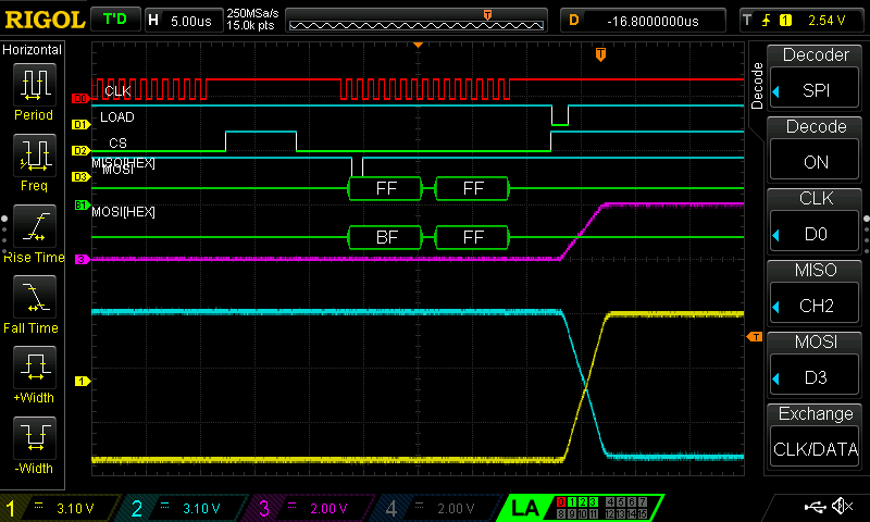
Here's a scope screenshot showing SPI data being sent to the DAC. The DAC output we're following is channel 3, the magenta line. The SPI command 0xBFFF causes to the output to transition from 0x000 to 0xFFF. The transition from min to max value takes about 6uS
Channel 2 (light blue) is the signal inverted and amplified, then channel 1 (yellow) inverts the signal again.
Over a longer period, we can see the differential output on channels 1 and 2 following the DAC output on channel 3:
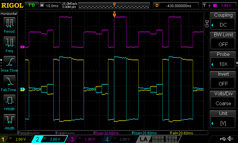
Notice that the op-amp output tends to drift toward 0V over the course of a few milliseconds. That's interesting.
Conclusions
One thing I learned: the output pattern is reasonably stable despite not having a separate 3.3V supply for the analog circuitry.
Things to do next:
- Start sending patterns from the RPi to the PIC32.
- Solder up the laser fet to a laser so the dot can be turned on and off.
Questions to answer some day:
- Measure the +/- 8 V and +/-15V rails while the galvos are operating. Is it noisy? Could the op-amps work directly with the 15V?
- How much of the overshoot is due to the settling of the op-amp output?
- Is the Y-galvo's overshoot problem specific to (a) the galvo, (b) the driver/amplifier board or (c) the output from the Frame Driver?
Discussions
Become a Hackaday.io Member
Create an account to leave a comment. Already have an account? Log In.
[this comment has been deleted]
I'd love to see a picture of your setup!
Are you sure? yes | no
Nice update. The corner stuff looks a lot like what laser cutters have to deal with (speed/power through corners, etc)
Are you sure? yes | no
Yes! The mass being moved is smaller than in a laser cutter, but the power used to control it is also lower. It's easy to imagine that momentum is an issue.
Thank you for your encouragement.
Are you sure? yes | no