Alan Green
-
Frame Driver Schematics
06/22/2019 at 03:04 • 0 commentsFollowing on from last posts' high level design, I drew up schematics. I like to keep each part of the schematic down to about one A4 page, so I can easily print it all.
These schematics represent a point in time. The will change as the project goes on. When I'm finished I'll upload them in full.
Voltage Shifter
The voltage shifter takes the DAC_X and DAC_Y signals, and turns each into a differential pair suitable for input to the galvos.

Based on my experiments with the signal generator, I don't need the full galvo deflection range, so I decided to go for an +/-8V differential range rather than the full, standard +/-10V range.
Generating the signal is two step process:
- We take the DAC's output range of 0-2V, and map it over the range 4V to -4V using one op amp. I
- We then find the inverse of that signal by using an op amp in standard inverting buffer configuration.
In step 1, we map the DAC's range somewhat upside down, by mapping 0V to 4V rather than -4V. The reason for this is that the op-amp configuration is more straight forward this way. Since we are always going to need both the positive and negative signal, it doesn't matter at all which we calculate first.
I used the site earmark.net to understand the required amp configuration and calculate resistor values. Bruce Carter has been extraordinarily generous in providing this resource.
[Parenthetic note: the DAC's actual range is 0.01 to 2.048V, but using 0-2V significantly simplifies the selection of values. I'm using 1% resistors, so the error from this simplification is much less than the accumulated error from other sources.]
MCUs
The PIC32 has some requirements, handily documented in section 2 of its datasheet. At least we don't need an external clock crystal. The Raspberry Pi comes with all its own support circuitry and the schematic just shows the Frame Driver's connections to the RPi's I/O header.

In addition to the usual bypass caps, the PIC32 requires:
- a small reset circuit,
- an expensive 1uF tantalum capacitor on Vcap to stabilize the internal LDO power supply.
There are also a couple of buttons and LEDs for debugging purposes.
(Looking at the schematic, I can see I'll likely want to add a reset push button, too. )
DAC and MOSFET
These are devices the PIC32 sends commands to, in order to drive the galvos and laser.

We power the DAC from a special 3V3 supply (3V3Ref) to help ensure the stability of its internal voltage reference. 3V3Ref is also shared by the voltage shifter.
The DMN2046U N-channel MOSFET controls power to the laser. Because the FET has ~300pF of capacitance, there's a 100Ω resistor inline on the LASER_FET output pin to reduce maximum output current to a peak of about 33mA - which is still twice the "maximum allowed" of 15mA. (Interesting discussion about gate resistors on Stack Exchange.)
Power
In previous projects, I've been bitten hard by noisy power supplies. This is likely overkill, but I'll start from here and then maybe experiment with removing some of it.

I am using an 7808 and 7908 to generate +/-8V from the galvo's +/-15V supply. The values of capacitors were taken from the datasheets, but I don't think they're particularly critical. The +/-8V is used to power the op-amps. While the op-amps can happily use +/-15V, its not clear to me that the power supply would be clean enough, especially when the galvos are under high load.
3V3Ref is generated from the RPI's 5V supply. It's purpose is to be a clean 3V3 supply for the DAC and to be used as a reference by the op amps.
Next steps: soldering!
-
Frame Driver High Level Design and Component Selection
06/15/2019 at 02:53 • 0 commentsThe purpose of the Frame Driver is to receive a "frame" of data from the Raspberry Pi and then output it until it receives a new frame. The Frame Driver will guide the laser beam around a path over the course of 1/30th or 1/50th of a second, turning the beam on and off as appropriate, and then do it, over and over again.
There are several steps between receiving a frame from the Pi, and outputting voltages to the Laser Galvos.

Frame Driver and its components Microcontroller
I've decided to use a PIC32MX170F256B-50 microcontroller. There were several reasons:
- The PIC32 is big enough that things are easy. It's definitely possible to do this with a smaller controller - see cfavreau's Arduino-powered Open Laser Show DAC - but I didn't want this to be hard to program, and I have no intention of large-scale production. 50MHz, multiple SPI peripherals, 64k of RAM and 256k of flash is more than enough. Cheap 32 bit arithmetic will likely help, too.
- The PIC32 is a relatively simple, controllable processor. I will be able set timers and handle interrupts to microsecond accuracy. The problem with Raspberry Pis and BeagleBones in this application is that they multiplex so much that they are no longer able to faithfully handle strict timing requirements. Listening to Bart Dring on The Amp Hour #438 talking about the ESP32 GRBL interpreter, the ESP32 could probably handle the timing requirements, but it's not trivial.
- I've been wanting to learn PIC32 for a while now.
DAC
I chose MCP4822 dual 12-bit DAC. It has an internal 2.048 voltage reference and has an SPI interface.
In this post on laserpointerforums.com, the consensus seems to be that an 8-bit DAC is not sufficient, but that a 12-bit DAC is plenty. 12 bits gives 4096 steps, which would be somewhere between 0.2 and 0.4mm per step on my kitchen wall, which seems sufficient, especially given that the laser beam is 1-2mm mm wide. Beyond 12 bits, things start to get quite pricey, and there's little additional advantage in having 0.05mm precision over 0.2mm precision at normal view distances.
For the cheaper DACs, there are two common standards for loading data: I²C and SPI. Generally, SPI is a faster protocol, both in terms of physical link speed and in having a lower protocol overhead. The MCP4822 can transfer data with a 20MHz clock and I am expecting to be able to use at least 5MHz.
Outputting two values from the MCP4822 DAC requires two 16 bit SPI transfers and then setting the LDAC pin low. At 5MHz, this will take (16 * 0.2 * 2 + a bit)μs ~= 8μs, which is fast enough. The DAC requires a "typical" 4.5μs to change its output signal from one level to another, anyway.
To ensure that the internal voltage reference is stable, a very stable power supply is required.
Voltage Shifter
The final component in the Frame Driver is the voltage shifter which takes two single-ended 0-2.048V signals and amplifies them to the +/-10V differential signals (maximum magnitude of any given line is +/- 5V) expected by the Galvo controller boards. It will be composed of 4 op amps, in a single package. I chose the TL084, because cfavreau used it successfully in his Open Laser Show DAC. It's also the same part used on the Galvo driver boards.
Power
Finally here is how I plan to power each of the components:
Component What it Needs How it Will Get it PIC32 3.3V, < 100mA. Pull from RPi 3.3V pins MPC4822 3.3V, a few mA, low ripple Dedicated 3.3V regulator running from from RPi 5V pins TL084 + and - 8V supplies, <20mA Dedicated regulators running from Galvo +/-15V supply lines. -
First Light
06/08/2019 at 11:22 • 0 commentsIn which I wire up the laser galvos in minimal way, validate some concepts and learn some new things.
![]()
Turning on The Galvos
Here's what I did. At each step I was careful to test to make sure that no smoke came out and that everything behaved as expected.
- Wired up the power supply to a mains plug,
- Connect power to the driver boards
- Connect the driver boards to the galvos
At that last step, the galvos moved! I had not been expecting them to move, but it seems that their off position is at one end of their range.
At this point, I used Blu-Tack to hold everything down, just to make sure nothing got lost in the tangle of wires. These are the grey blobs you can see in the photos above.
I then stole the cat's spare laser pointer, Blu-Tacked it in place and lo! there was a dot.
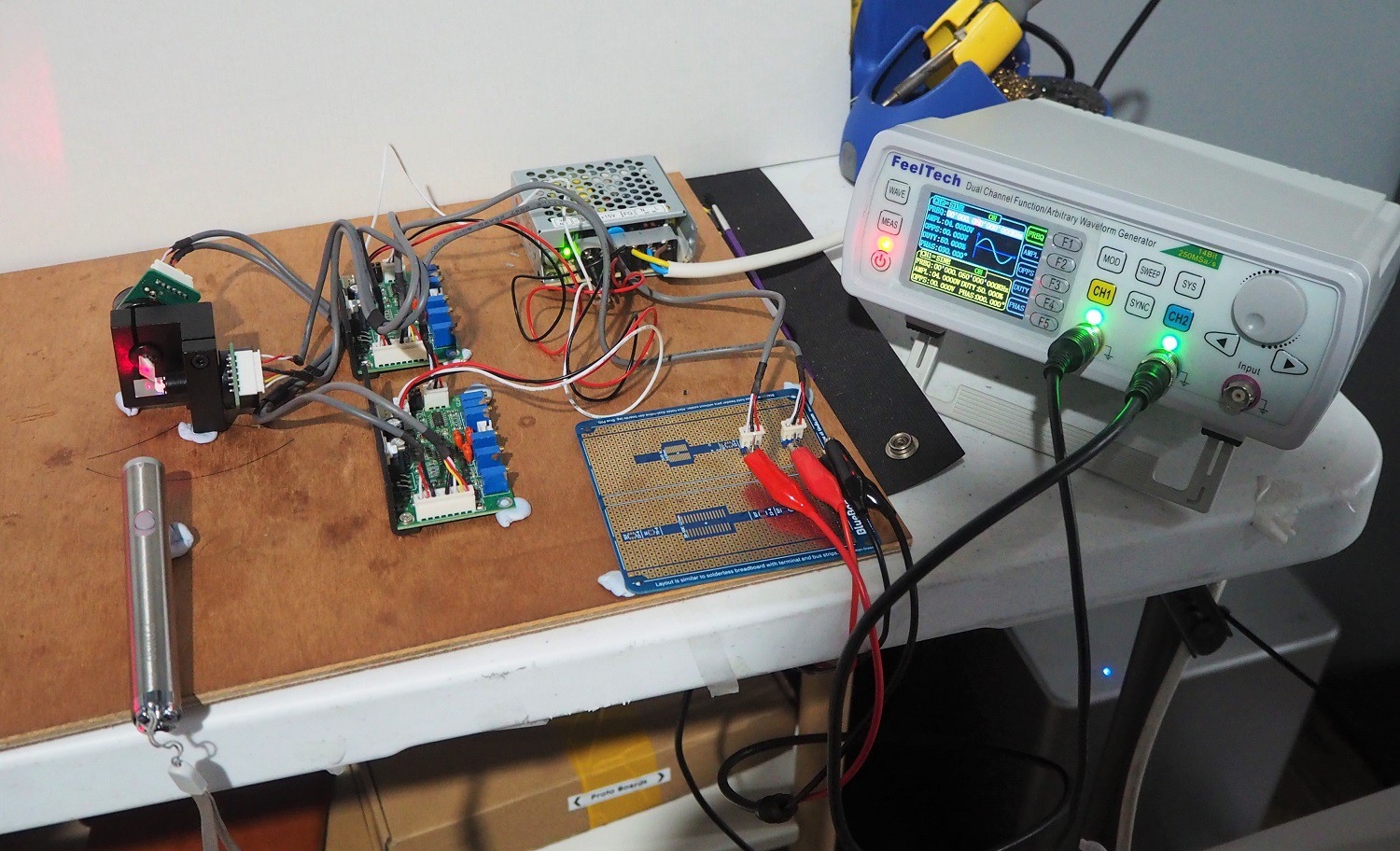
Signal Generator and Pretty Patterns
I have a dual-channel signal generator. Using a Blue Board #01 I soldered up a couple of connections. Each driver board is fed by three wires: ground, V+ and V-, with V+ and V- carrying a differential signal of up to 10V. I tied each driver board's V- signal to ground, then piped in the signal to V+.
The resulting patterns look different on camera than they do in real life, but are interesting nonetheless. The shapes are correct even if the colors are not.

The ABC of Lissajous 
Space uniform logo 
Neon crochet pillow Here are some things I learned:
- The upper frequency limit is around 1kHz. Above that, the range of movement becomes limited.
- Above 500Hz or so, the movement of the galvos makes an audible sound. The sound becomes louder with higher base frequencies, with larger signal amplitudes and with more complex waveforms, especially those with higher frequency components.
- The driver board heat sinks get quite warm.
- The power supply does not really get warm
- 50Hz is plenty for making a stable looking image.
- The mirrors and galvos have momementum and it causes overshoot and undershoot. Any drawing sequence is going to need to take these physical effects into account because it's not like drawing pixels on a screen.
- I will need a higher power laser for day time viewing. The cat laser is going strong after several hours.
I think this is going to work!
-
Looking at the Galvos
06/08/2019 at 05:43 • 0 commentsWhat I Bought
I bought the cheapest laser galvo mirror set that I could buy, that also had reasonable shipping. I ended up with this one.

The kind I bought The set comes with the twin galvanometers, mounted on a metal block, two driver boards and a power supply. It cost about 100AUD on eBay (listing). Several of the sets on sale also offer a "show card", which will run laser displays from an SD Card. I wanted to build the display logic myself, so I didn't buy a show card.
The specs from the listing are:
-Input voltage:15V
-Peak current: 1A
-Rated current:0.5A
-Operating temperature:0~50℃
-Rated scanning angle:± 20 °
-Maximum scanning angle: ± 30 °
-Drive plate size:76mm × 48mm × 26mm
-Wavelength:380nm-700nm
-Analog signal input impedance: 200K ± 1% Ω (differential input)
-Analog position input range: ± 5 V.
-Scanning speed:20Kpps
-Lens reflectivity:> 98% @ 45 ° incidence (coverage wavelength: 380nm-700nm)
Important to note here:
- They are rated for 20kpps (20,000 points per second) at 20°. Here is a description of how that test is supposed to have been done. Note that, at the rated speed, the produced pattern looks different to how it does at a lower speed. The galvo mirrors aren't magical after all - they take a finite amount of time to move into position.
- The galvanometers are rated as consume 1A 15V, peak. That's quite a bit. One can see why a driver board is required.
- Input impedance is high, which is good.
Given the amount of power consumed, I think it's probably a good idea to aim for smaller angles of defletion and slower scan rates.
Power Supply
The supply came with two 3 pin connectors pre-attached to the output screw terminals. I confirmed with the multimeter that FG is connected to the chassis, while N & L are not. The G terminal is not connected to FG or to N (or L!).

Supply and Connectors Label on the power supply says it supplies 1A at 15V, which nicely matches the peak current draw spec.

There's quite a difference between input power rating (0.5A@100V = 50W) and output rating(1.0A@15V + 0.5A @ 15V = 22.5W). I suppose this means that the supply gets hot.
This is all about what I expected.
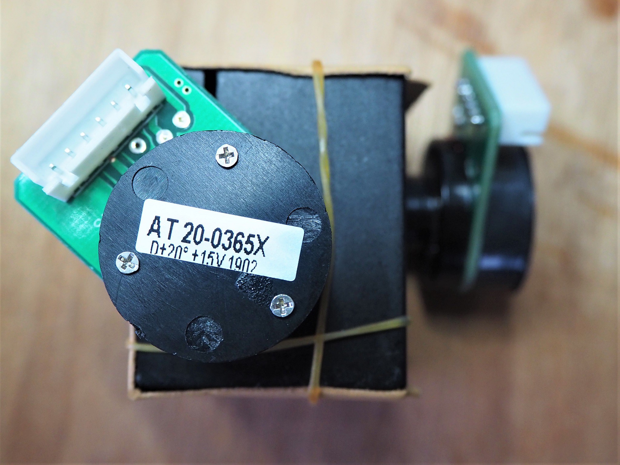
Galvos and Mirrors
As noted above, the galvanometers are firmly aligned in a metal block. Under the block are screw holes which are obviously useful for securing the block.

The interesting bit Hmm... looking at the photo, that mirror seems a little dusty. I'll need to clean them. The galvanometer PCBs each have the galvanometer, the connector, and nothing else:
![]()
I'm not entirely sure why the connectors have 6 terminals each, but based on the cables, I'm guessing the galvos give some kind of feedback to the driver board.
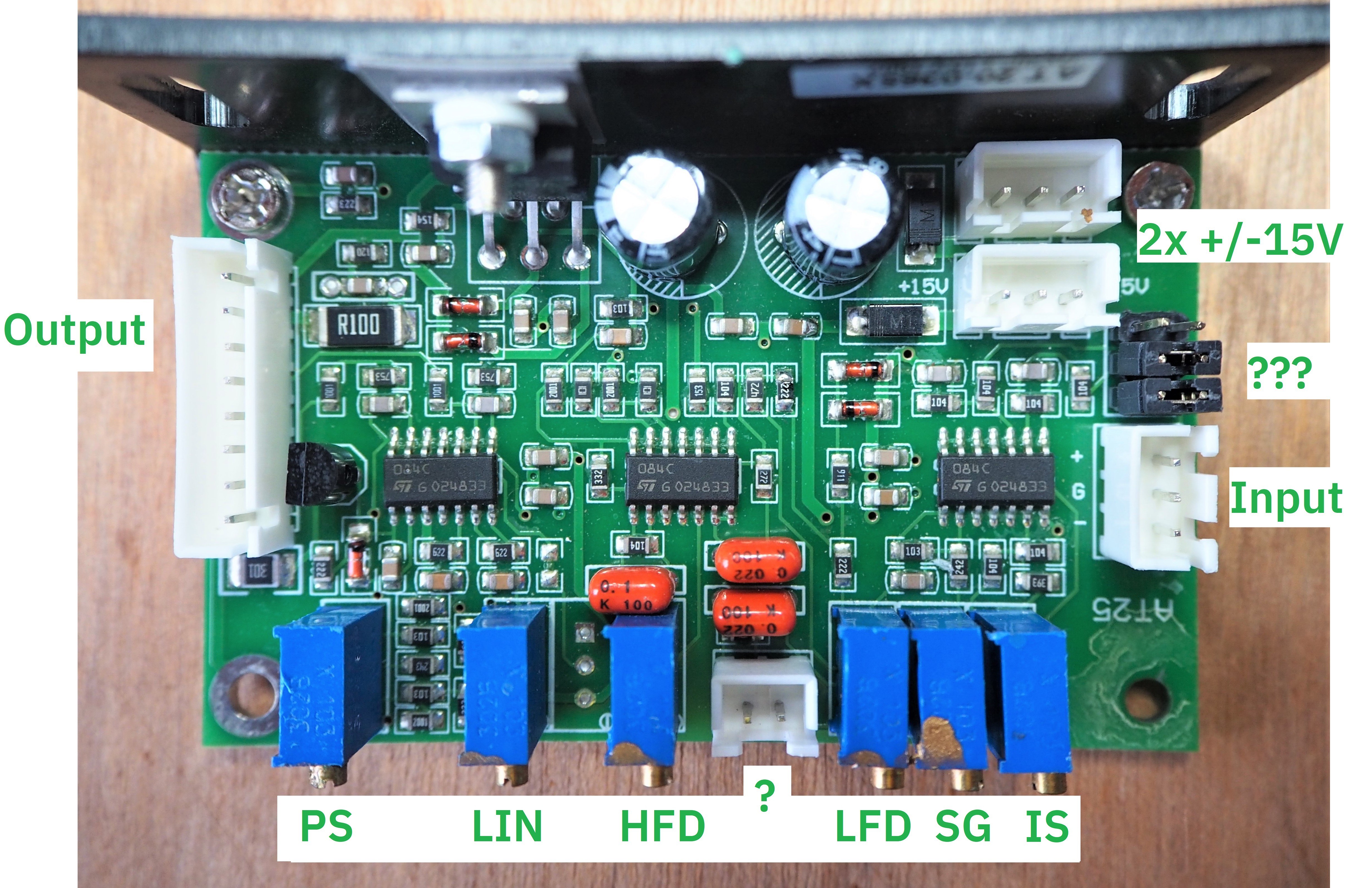
Driver Boards
These boards are responsible for amplifying a high impedance, 10V differential signal into a low impedance 15V signal.
![]()
I've marked the connectors with their apparent function. There's signal input, two power connectors and an 8 pin output connector. The picture at the top of the page shows the cables that run between the 8 pin output connector on the driver board and the 6 pin connector on the galvo. The conductors run in two bundles.
Trimpots and Unknowns
The trimpots along the bottom each have two-letter markings on the underside of the board. I've put these markings in the picture. Based on this Aliexpress listing for a similar product, I'm guessing the meanings are:
- PS = Position Scale
- LIN = Zero Offset
- LFD = Low Frequency Gain
- HFD = High Frequency Gain
- SG = Servo Gain
- IS = Input Scale
All of them appear to be locked with a small amount of glue, except Input Scale. I won't touch any of them.
There is a 2x3 header area with two jumpers on it, next to the input. No idea what that is for.
Similarly, there's a 2 pin connector in between the trim pots that I have no idea about.
ICs
The 3 14-SOIC packages on the driver board appear to be TL084 Quad JFet Op Amps (datasheet), which cost about 0.20USD each, in quantity. They have a minimum rated output short circuit current of 10mA, which means they are not powerful enough to drive the galvos alone.
The back of the board has a vertical metal plate, which is used as a heat sink for a CD2030A audio amplifier IC (datasheet). It looks as though this amplifier was originally made by ST, and while it is now obsolete according to that manufacturer it is still being sold - and I am guessing still being manufactured - in China.
This amplifier is considered "pretty good for the price"... and the price is about 0.20AUD each.
The datasheet says it can provide 18W of power, and provide amplification up to 100kHz. This would appear to make it possibly suitable for driving galvos at 20kpps.
-
The Plan
06/08/2019 at 02:20 • 2 comments
Kitchen, with VR Overlay I want to replace our kitchen clock with one that glows in the dark. I was inspired by this instructable from DeltaFlo and encouraged by further write ups such as this one from Barton Dring and this one from Vulcaman.
Napkin Diagram

Current Thinking For someone of my skill level, this will be a complicated build:- I'm choosing Raspberry Pi for the controller. There are several other good options: Beaglebone might obviate the need for a separate MCU, ESP32 is cheap and in vogue right now. However, Raspberry Pi is well supported and has plenty of compute power.
- The Pi will have a physical and a web UI, accessible from the local LAN. The Pi will get its time from the internet.
- The Frame Driver draws the same thing over and over, until it's told to draw something different. It will be powered by a small microcontroller, and its output will be two ±5v differential signal.
- Complicated power supply. First, the Frame Driver's DAC will need a rock solid supply in order to accurately produce a signal for the mirror drivers. Second, that signal needs to be amplified from 3.3V to ±5v.
Questions To Answer
I will begin by addressing uncertainties:
- How good are the galvos and their drivers? What kind of accuracy can I expect in drawing?
- Do I need really to produce a ±5v signal, or is 0-10v good enough?
- What laser should I use? I want one that can operate continuously (for years, I hope!) show brightly and still be eye-safe.
- Where did I put that Raspberry Pi and its power supply?