Hardware
There are various aspects of this project on the hardware side of things, which will be discussed in this section. The microcontroller we chose to use for breakout testing was the Arduino Zero, which is built around a SAMD21 microcontroller made by Atmel. The Zero is more powerful than the common Arduino Uno and had enough I/O and communication (I2C and SPI) pins for our purposes, so it was not a difficult choice. We had originally begun to build the system using an ATSAM4S8B microcontroller from Atmel, but decided to switch to the Arduino after a few weeks once we realized that a great deal of the code we needed was provided by Adafruit and Sparkfun as example Arduino based code for our sensors. With the Zero having 3.3 V logic levels, we needed to make sure all the sensors we used were compatible with that. As an additional constraint, we were also looking for sensors that could communicate using I2C so that we would only need to worry about one data line and one clock line.
As a base for our sensors, we chose the BNO055 breakout from Adafruit because it offers a great deal, such as orientation and acceleration. When researching the BNO055, we noted that it has an acceleration limit of 16g, which would easily be surpassed in our usage, leading us to purchase a second, high-g tolerant accelerometer, the H3LIS331DL.
The H3LIS chip does not provide a great deal of accuracy but it does have very high acceleration limits, up to 400g. It can also survive a shock of 10,000g, which is a nice feature since rocket launches can sometimes go awry. With the high g-force tolerance, it was a good choice for a chip that would sense the rocket being launched by detecting acceleration and waking up the system from low power mode.
The BMP388 is used to track the altitude of the rocket. The altitude a rocket reaches is an important characteristic of the flight as the rockets are often intended to reach a very specific height. The BMP388 is pressure based so it needs to be calibrated with the daily barometric pressure at sea level if the user wants the absolute altitude to be correct. Otherwise, without calibration, the absolute altitude will be incorrect but the relative altitude will still be correct. For our purposes, we only need relative altitude to know the apex that the rocket reaches, so we had no need to calibrate it daily. The BMP388 is accurate to ±0.5 m, meaning it provides an extremely accurate reading.
One of the main features of our system is the GPS tracking of the rocket, which is done by the SAM-M8Q GPS unit. The main purpose of the GPS is to locate the rocket after the flight, which can sometimes be difficult. Currently, the main method of rocket retrieval is using a handheld detector, which can be a very cumbersome process. With the GPS unit in place, one could simply pull the coordinates off the website and know exactly where the rocket is immediately. The GPS unit we chose has horizontal accuracy of 2.5 m, which is more than enough to find a rocket when looking for one. It also has a maximum altitude of 50,000 m, which the rockets we are using will never come close to.
The next piece of hardware we used was the Sparkfun Battery Babysitter, which consists of both the BQ24075 battery charger and the BQ27441-G1A fuel gauge. The Battery Babysitter is used to charge and manage the 3.7 V 1200 maH lithium ion polymer battery, which powers the whole system. The battery can be charged at different rates, which are selectable by switches. With the battery plugged into the Battery Babysitter, the charge can be read directly over I2C based on the mA currently being used by the system.
As a method of storing data, we included a microSD card chip along with everything else. While all the other chips have used I2C so far, the microSD card is written to using SPI. The Arduino Zero has a dedicated SPI header which was very easy to interface with. The microSD breakout has a dedicated level shifter, which provides much faster read/write access than if it had been done with resistors. The microSD card itself holds all the data recorded during the flight, such as GPS locations, acceleration, orientation, and battery charge. With the data recorded on a microSD card, it's easy for the data to be charted and analyzed afterwards in an Excel document, which is often done after a flight to analyze certain characteristics of the flight itself. These data can also be compared to one another in order to decide between parts, such as which motor provides faster acceleration at launch.
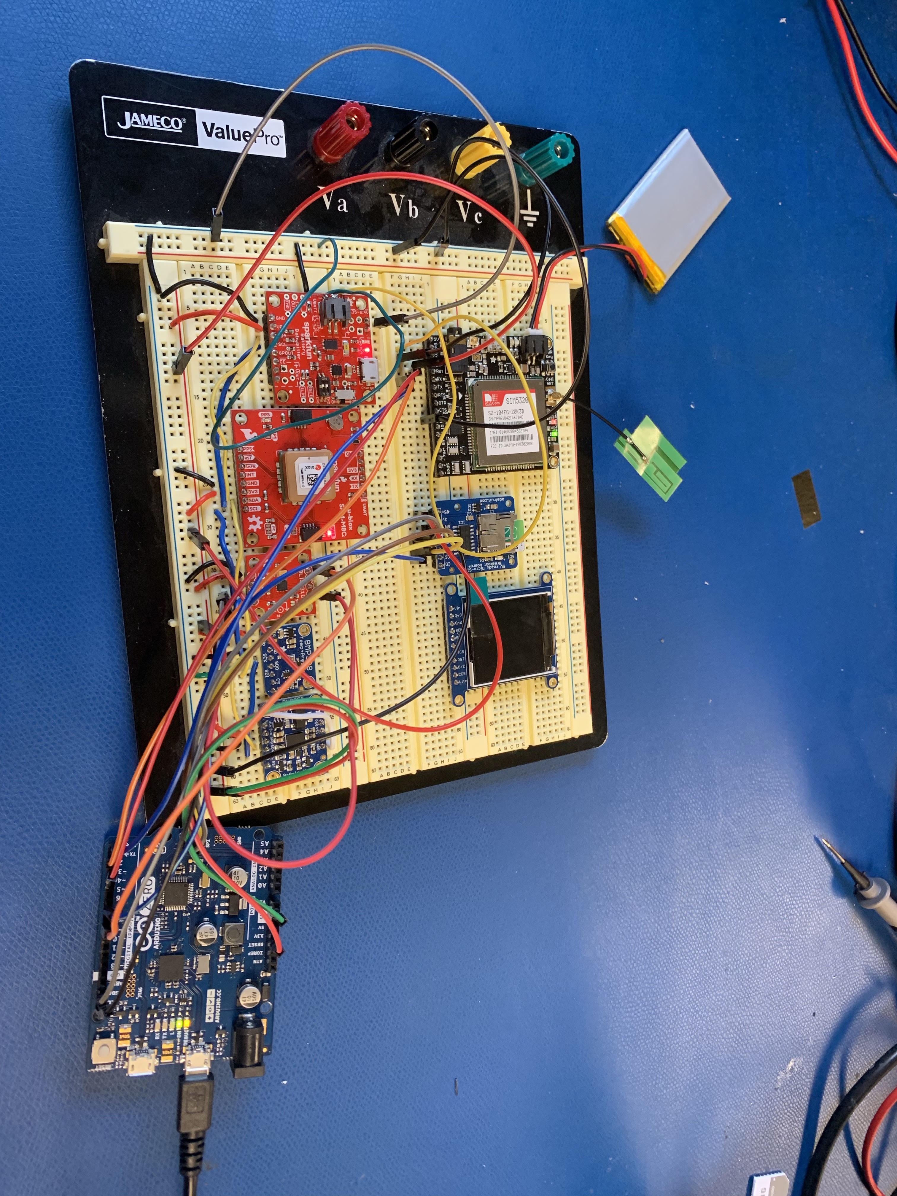
The final piece of hardware was the LTE chip, the SIM5320A. We communicated with the LTE breakout using UART. It was definitely the most time consuming portion of the project. The LTE breakout requires an antenna and a SIM card in order to function. We purchased a GSM antenna from Adafruit along with a SIM card from AT&T to use with the LTE chip. When first testing the LTE breakout, we communicated with it directly to ensure that we had a handle over the AT command set. Once we ensured the commands were working correctly, we wired the LTE breakout to the Arduino Zero using UART. We then used an example sketch from Adafruit to test our cellular connection and were able to send texts and make phone calls. With the cellular connection active, we tested with AT commands until we were able to successfully post data to the website using the LTE chip. When we mastered this process, we built the functionality into our code and were able to read data from the sensors and send them to the website over the 3G network.
The image below shows the final breakout system:
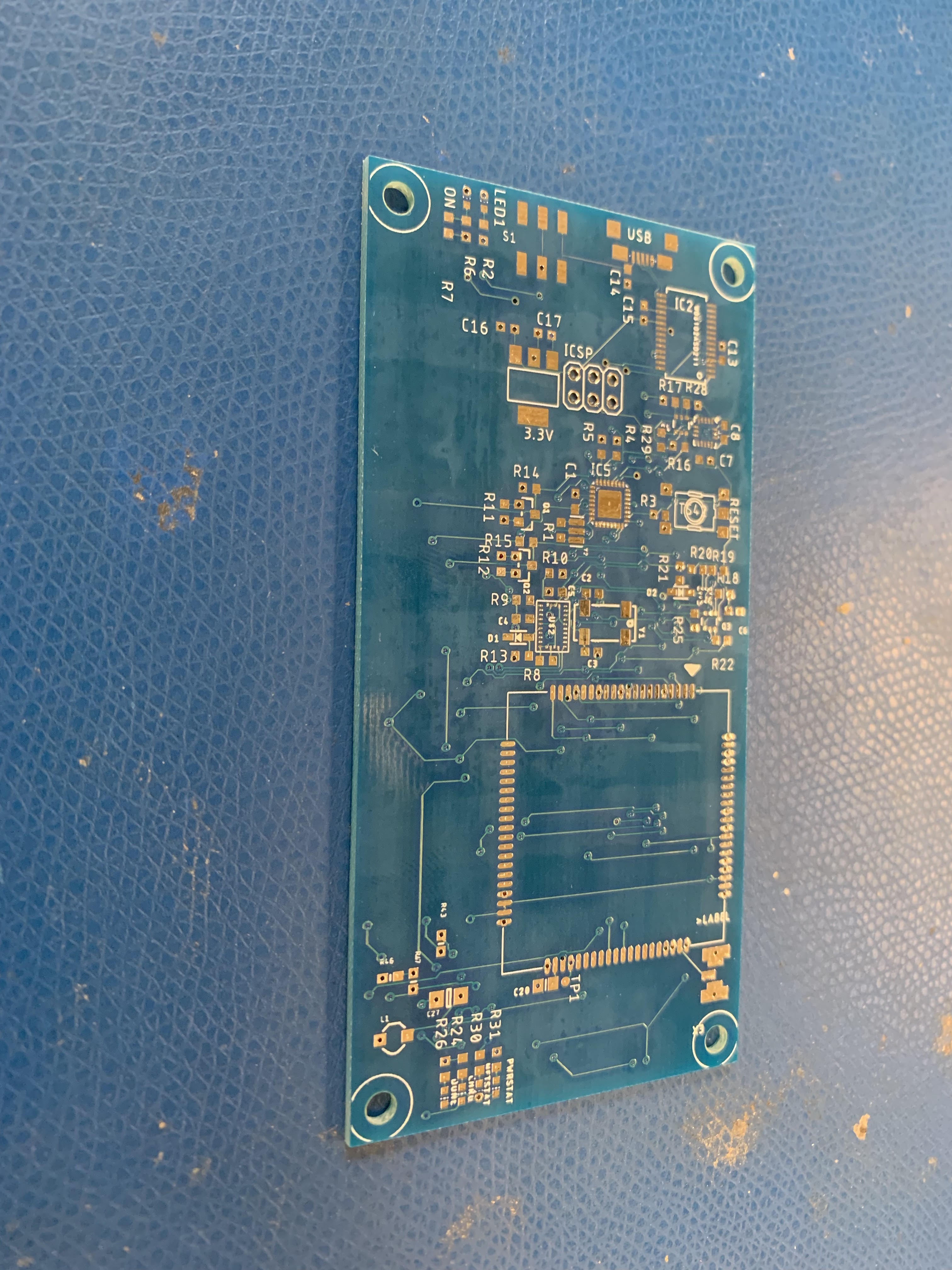
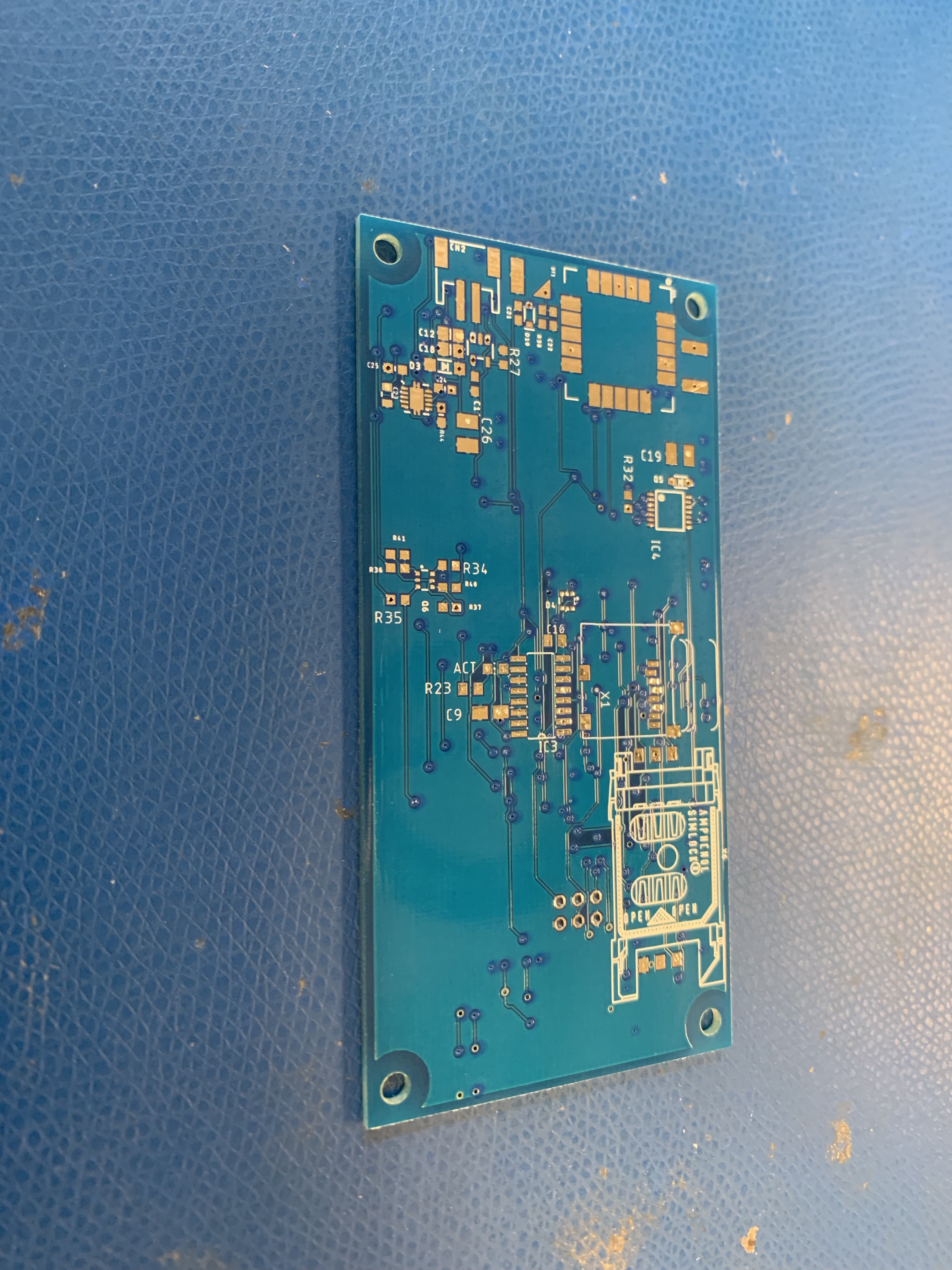
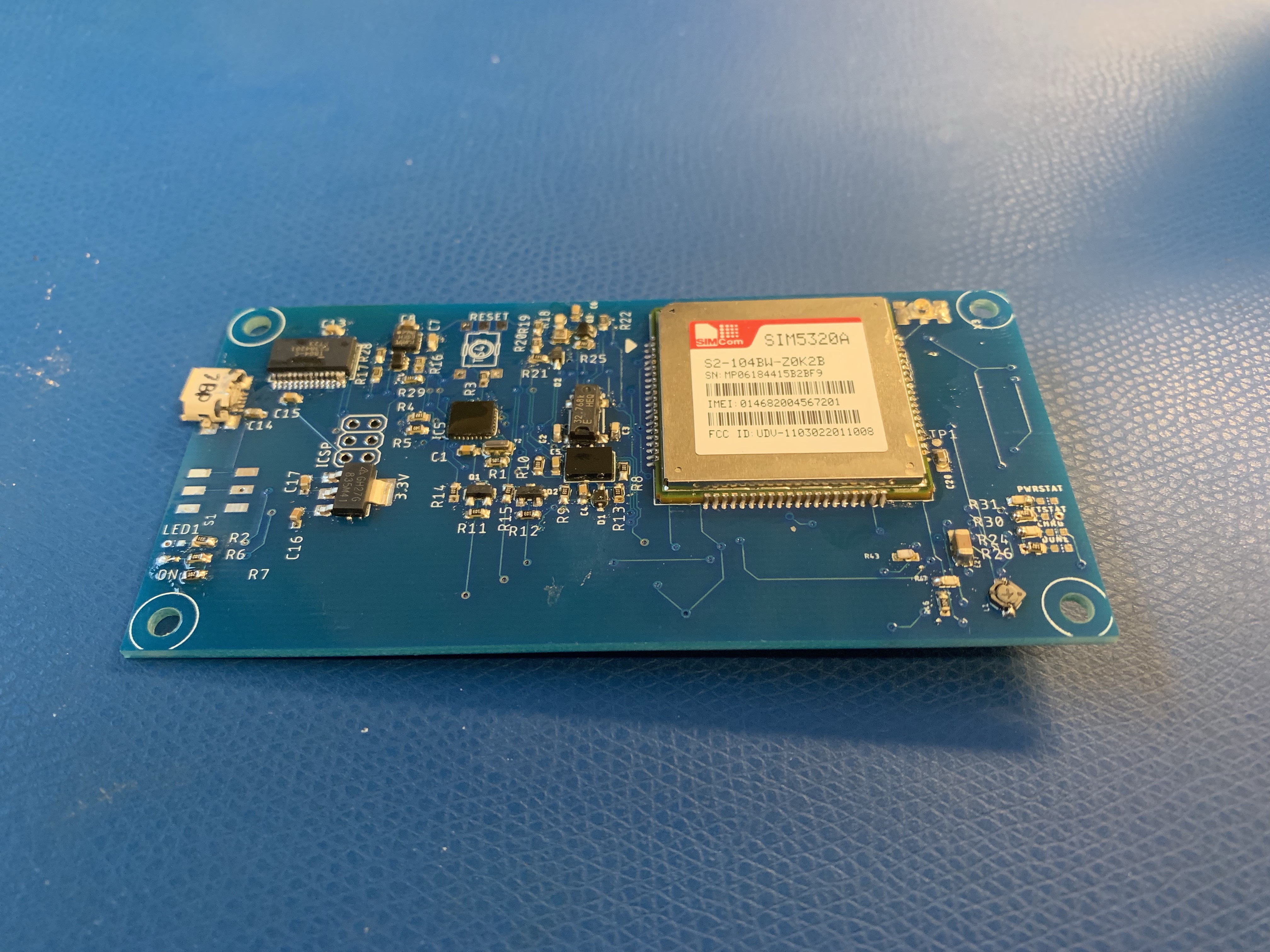
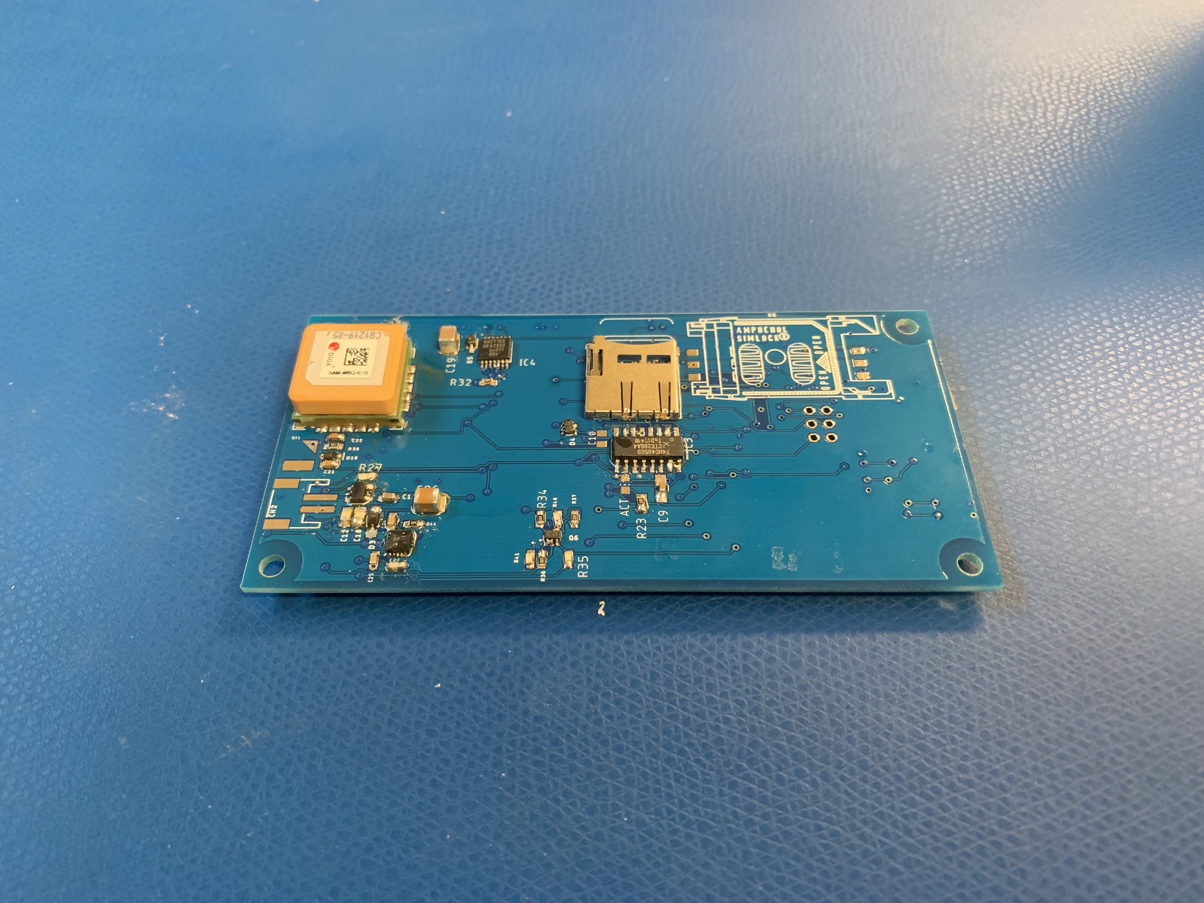
While we were working on making the breakout system functional, we also developed the PCB for our final product. This was created by taking the breakout chips and recreating each one altogether on a single PCB. We chose to make most of the board surface mount due to the easier soldering method when dealing with a great number of components, although we did use a few through hole components when necessary. Due to the size of some of the components (mainly the SIM5320A cellular module), the final size of the board came out to 10 cm x 5 cm. Since we changed to the Arduino Zero a few weeks into the project, we spent much of our time finalizing the breakout system to get it into a working state. With the time we put into the breakout system, we were quite near the end of the quarter when we were finally able to test the PCB. Unfortunately for us, we made a few errors during the PCB design stage which prevented our board from working. Because the SIM card slot used by the LTE breakout was out of stock, we had to purchase a different one, which did not end up fitting our SIM card. With that major error and a few smaller errors, such as wrong connections, we never got a chance to fully test our PCB in a rocket, much to our dismay. We did, however, manage to get the breakout system to be fully functional, so we know how those wiring mistakes could be fixed in the future. The PCB layout and schematic can be downloaded in the "Files" section of this Hackaday page. Below are images of the unsoldered PCB and the soldered version with components that do not need to be fixed:
Software
We began the coding by taking all the example projects provided by Adafruit and Sparkfun and compiling them together into one script. We then moved through the code and got each sensor working one by one, including the appropriate libraries and modeling our code after the structure used in the example projects. With the BMP388 and BNO055, we had to modify a few lines of the libraries in order to get the sensors up and running. With each sensor, we read data and printed to the serial monitor as a check that everything was working properly. Eventually, we were reading data from all the sensors and printing it to the serial monitor. At this point, we used the FONA library from Adafruit and the AT command set we had previously developed to post the sensor data to the website. After some testing, we were able to post the GPS latitude and longitude coordinates, which could be used to locate the rocket.
After posting to the website, we then focused on the microSD card so that all the data could be stored for later use. We set up a datalogging function which, after the data were all read, would write everything to the microSD card in .csv format. The data are written just as often as the sensors are updated, which came out to about 1 Hz due to there being five devices on the same I2C lines and the time needed to write to the microSD card. The data are always written to the same file called "data.csv". Each time the system resets or is turned off and back on, the column headers are printed again to indicate a new run has started. The timestamp also resets to provide accurate data measurement times. Below is an image of the data from the sensors logged into the Excel spreadsheet. The GPS did not have a location fix because we were working in our lab, which is in the basement of the building:

Once the microSD card writing was completed, the final piece of coding was to set the system in low power mode whenever idle. We decided that an acceleration trigger would be the best method of taking the device out of low power mode. Due to the ease of enabling an interrupt on the H3LIS331DL high-g accelerometer, we chose to use that chip and set an interrupt on the acceleration. With that in place, we moved onto enabling the low power modes before the interrupt was triggered. To do so, we went one by one through all the components to determine if they had low power capability and, if they did, how to activate it. The BNO055 had a simple function to enter and exit low power mode, so it was done quickly. The BMP388 had no low power functionality because it takes very little power in its normal operating mode. The H3LIS331DL had a low power mode, but was being used to trigger the launch interrupt, so it could not be put into low power mode. The SAM-M8Q GPS unit and the Battery Babysitter both had no low power modes. The SIM5320A LTE chip did have a low power mode, but we could not use it because it takes too long to exit low power mode, return to standard operating mode, and begin transmitting data. With this in place, the low power mode was fully implemented. A video of the interrupt working to take the system out of low power mode can be downloaded in the "Files" section of this Hackaday page.