 danjovic
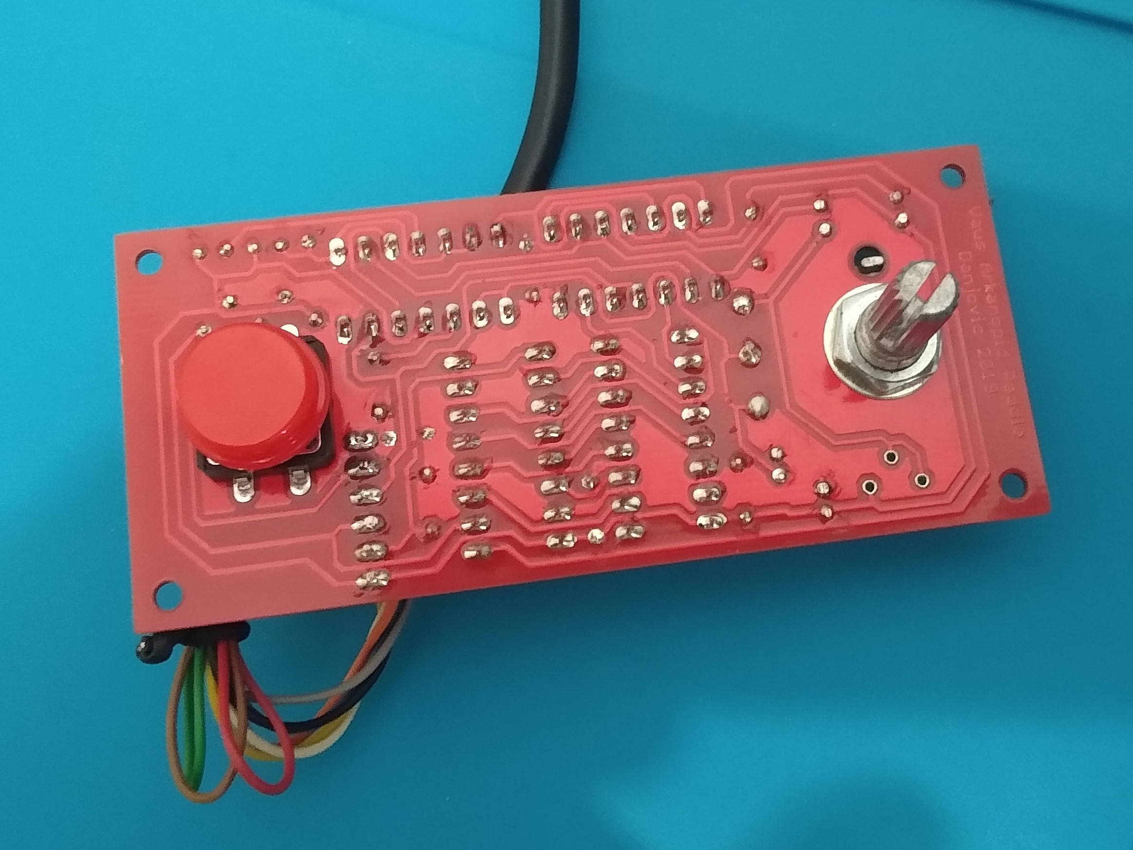
Here are some pictures of the board after assembly of the components.
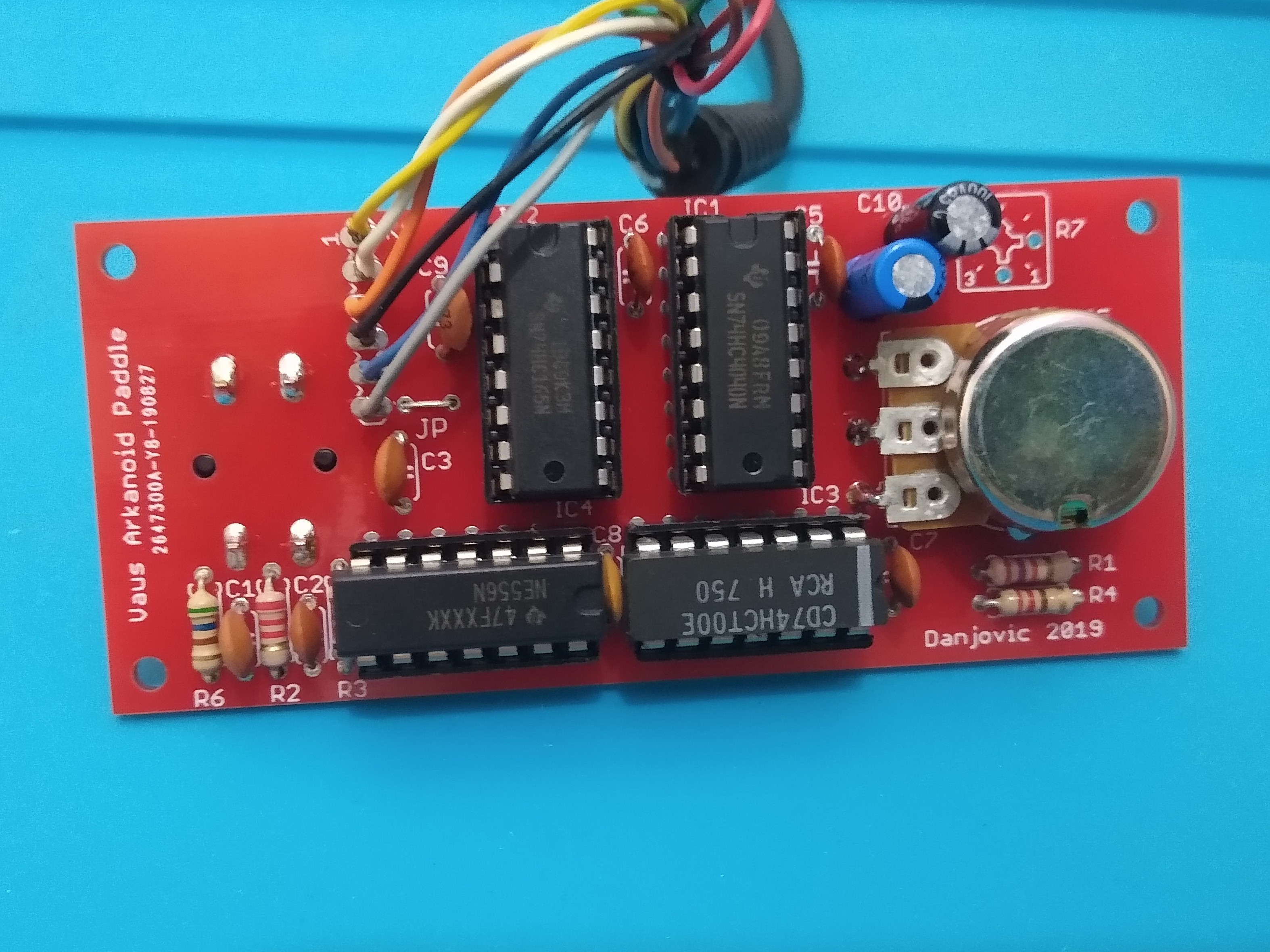
The potentiometer leads were too short to reach the board pads and required the use of some bare wire to extend them.
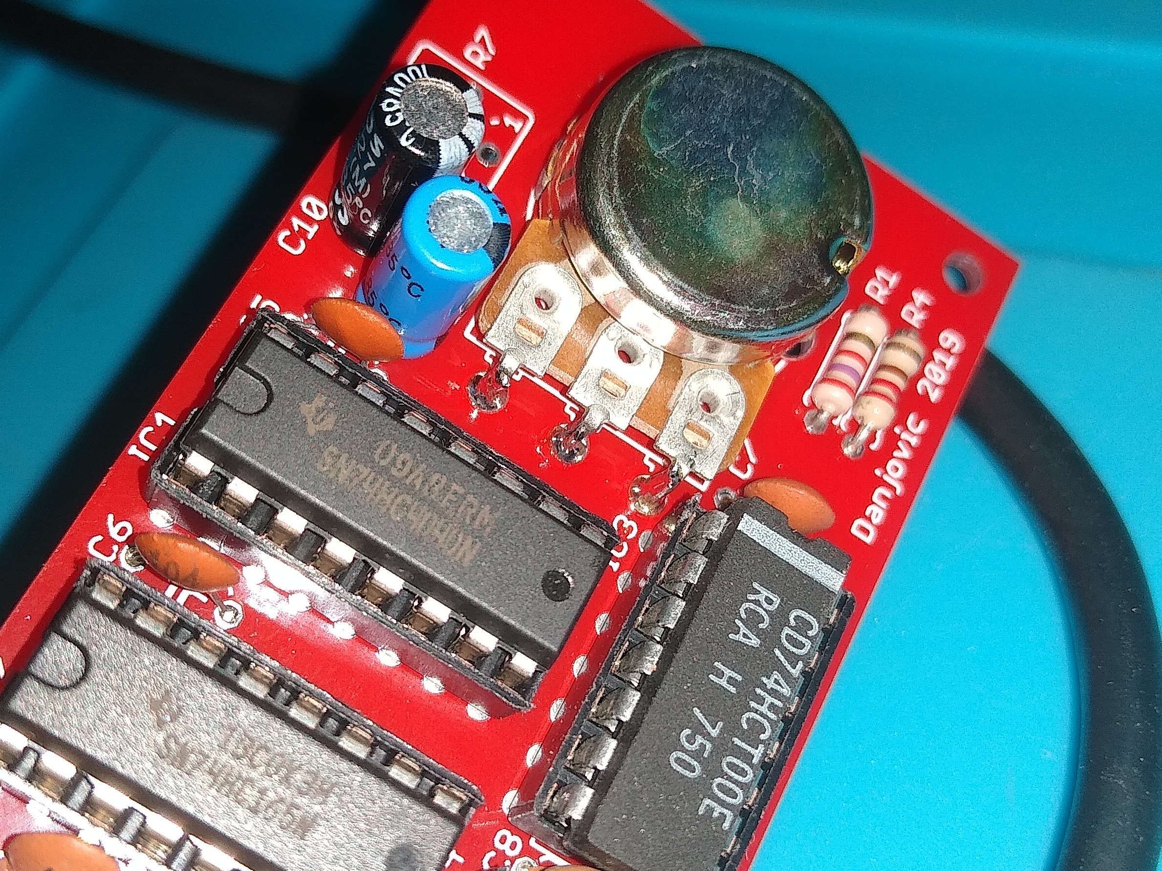
The potentiometer value used was 10k instead of 4K7, but the timing capacitor was reduced to 0,47uF to compensate.
Trimpot R7 is optional. Instead a 2k7 resistor was used for R1 and it provided a counting from 90 to 400 (approximately) which is right within the desired range.
Discussions
Become a Hackaday.io Member
Create an account to leave a comment. Already have an account? Log In.