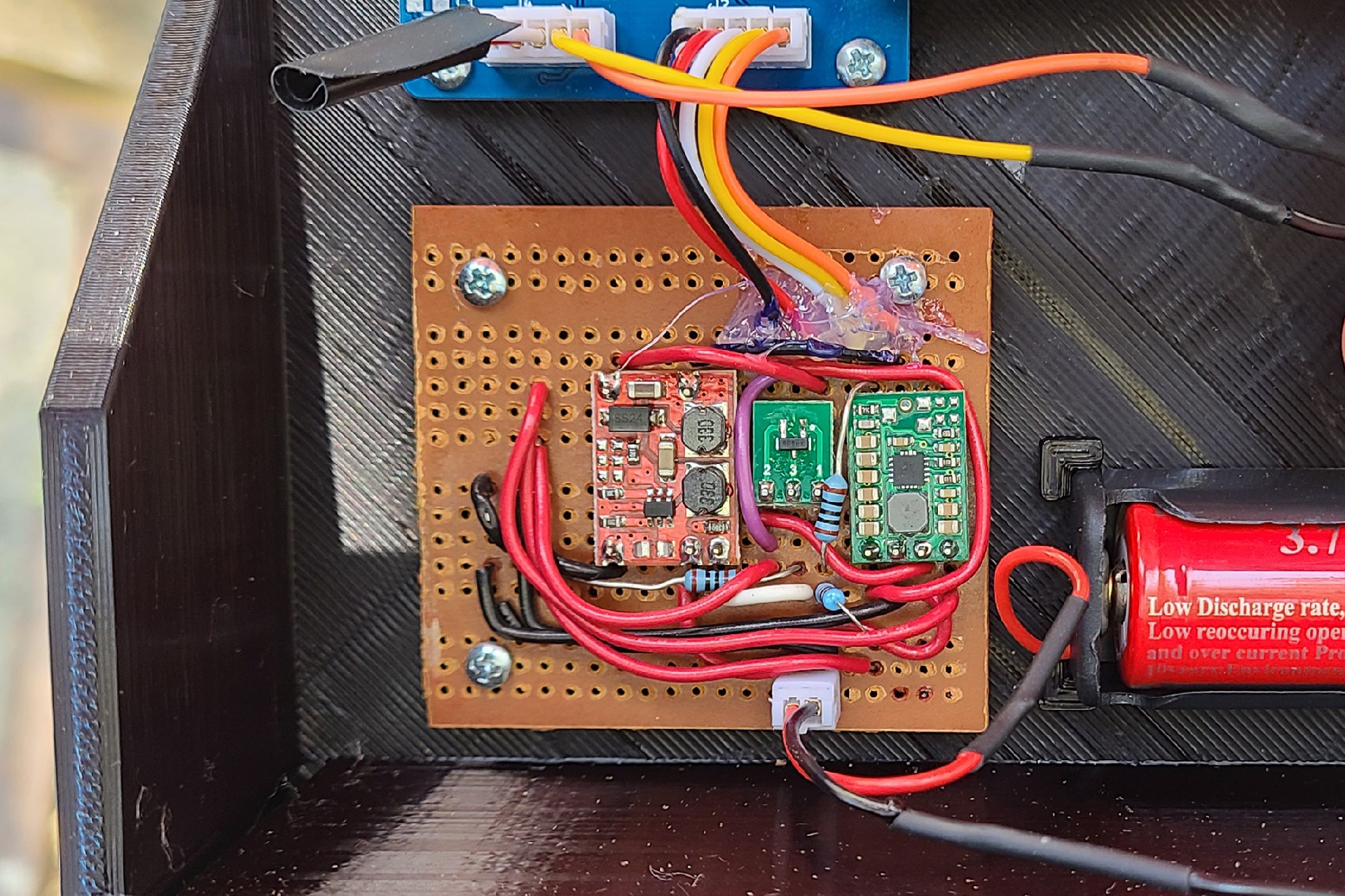
My initial design based on a TI TPS63000 buck/boost converter (for the 3.3V supply) and a Microchip MIC2288 boost converter (for 5V), turned out not to work very well once I got the PCB assembled. The MIC2288 drew several mA even when disabled so that wasn't battery friendly, and the I could not get TPS63000 to be stable.
I did find a 5V boost converter in my parts drawer which had very low current when disabled (the red PCB), so I soldered that and a Pololu S7V8F3 3.3V Buck/Boost Converter(the PCB with all the caps on the right) to a piece of Perf board to get my Mailbox sensor out the door. This combination has a quiescent current of about 50uA.
The 5V power supply is only used to power the IR LED for the proximity sensor, so it is normally disabled and a GPIO pin from the uC enables the boost converter when it needs to power the LED. I found when testing, though, that when the battery level was higher than about 3.7 V, the 3.3 V from the GPIO was too far below the 3.7 V Vin of the boost converter to turn it on. I had to add a MOSFET (the middle PCB) that could be turned on by 3.3V which would switch the battery Vin of the boost converter to the enable pin, so no matter what the battery voltage is, the enable GPIO will work.
As part of my weather station project, I have revisited the 3.3V buck/boost converter, and I now have a working version, and if I can get the solar charging working well in that project, I may retrofit solar charging into this project as well. As it is now, I monitor the battery voltage, and send an alert to myself if it falls below 3 V. At that point I will have to charge the battery, though, at the current rate of discharge, it should be about a year before that is necessary.

 Kevin Kessler
Discussions
Become a Hackaday.io Member
Create an account to leave a comment. Already have an account? Log In.