 Nicolò
To open the speaker you have to unglue the back plastic cover, to do so I have use ad heat gun ando some IPA, unfortunatly i don't had the correct nozzle/temperature combination and during the removal the back cover is now bended.
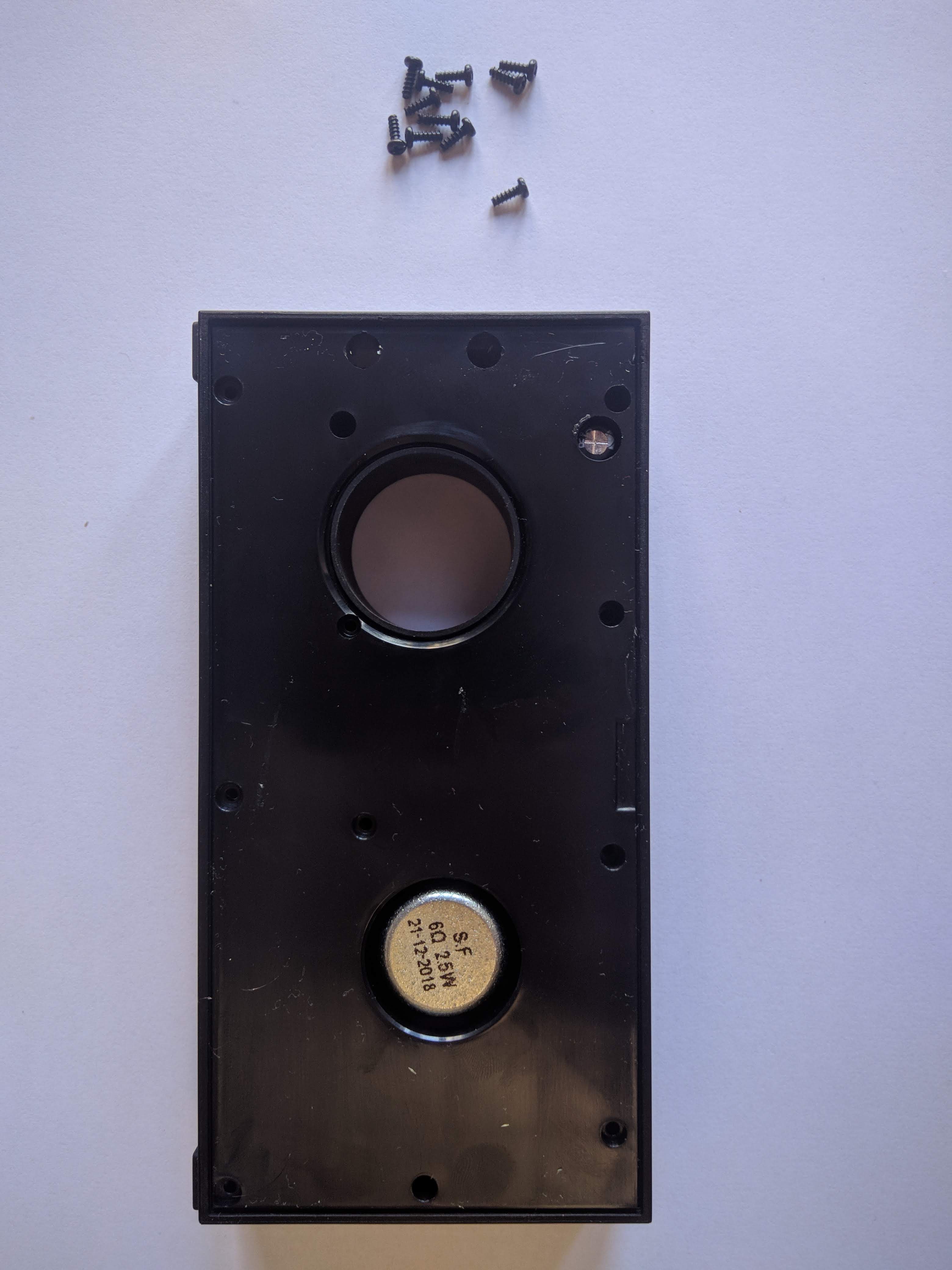
Below the cover you can find the scrws that keep the speaker together as a bick.
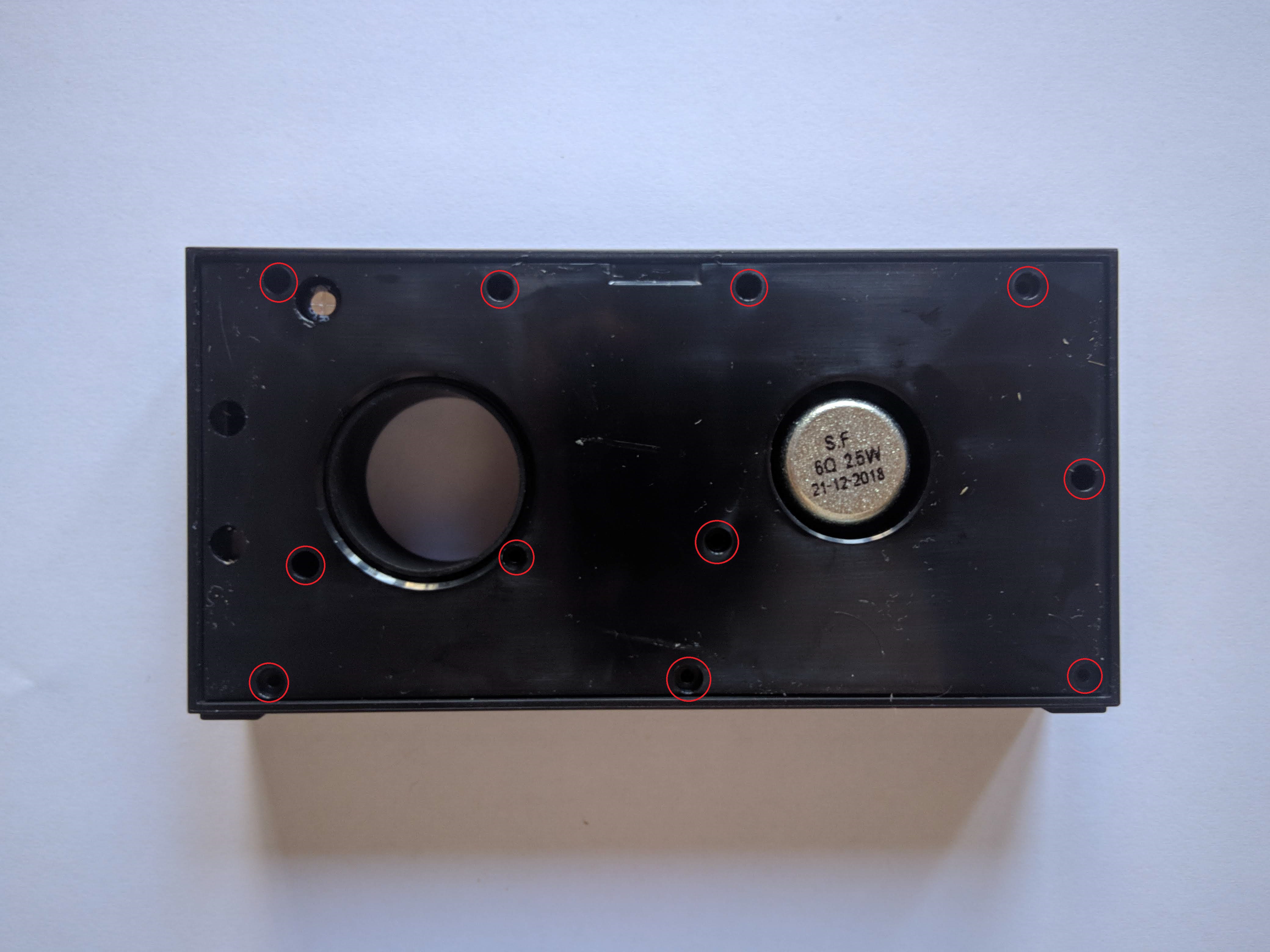
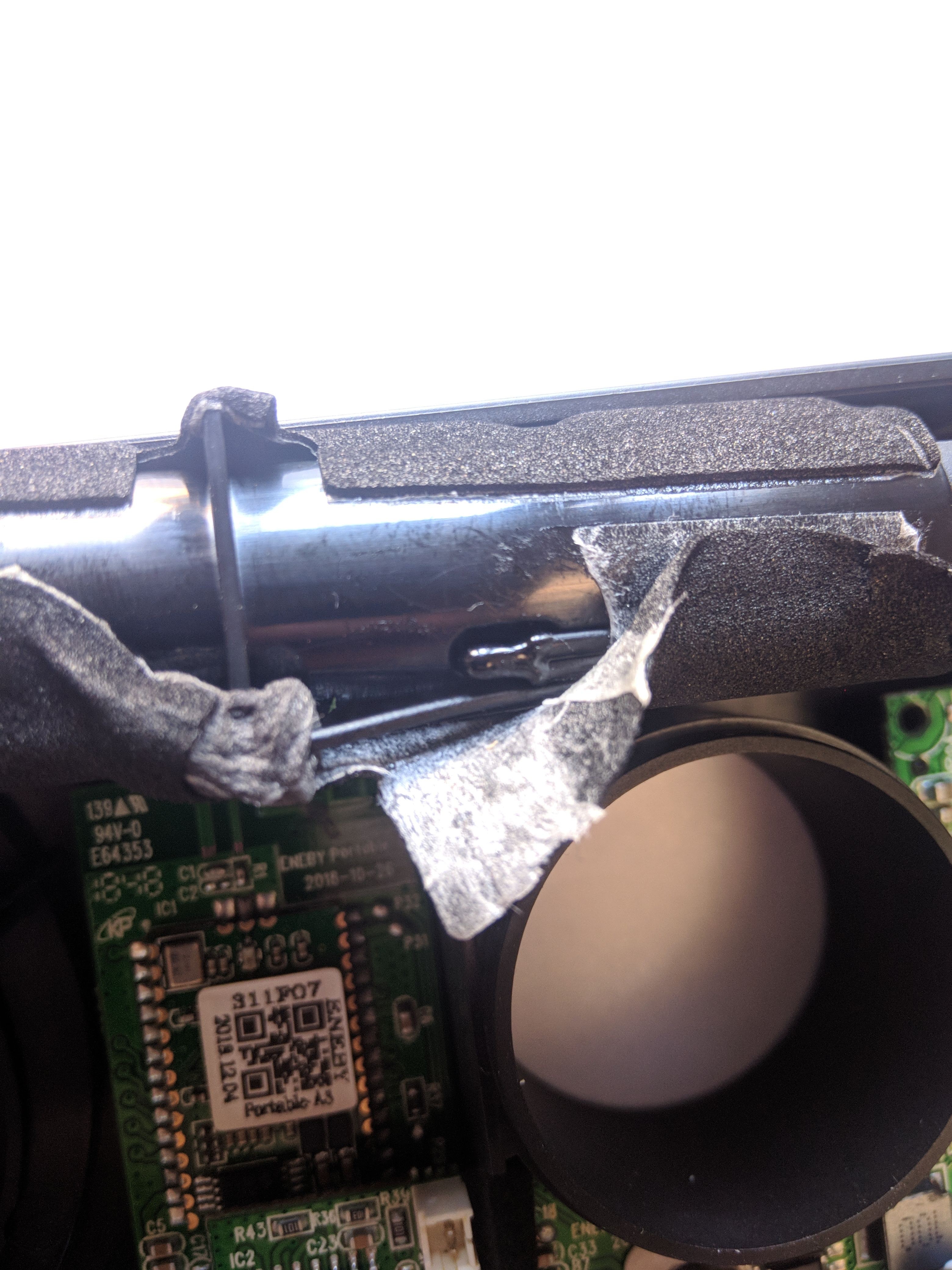
Once you remove the screws you have to apply some force to remove the back lid. The borders of that lid have a foam coating/tape to create a air tight chamber.
 In the folowing photo you can see with a bit more details the foam thy used to close all the gaps:
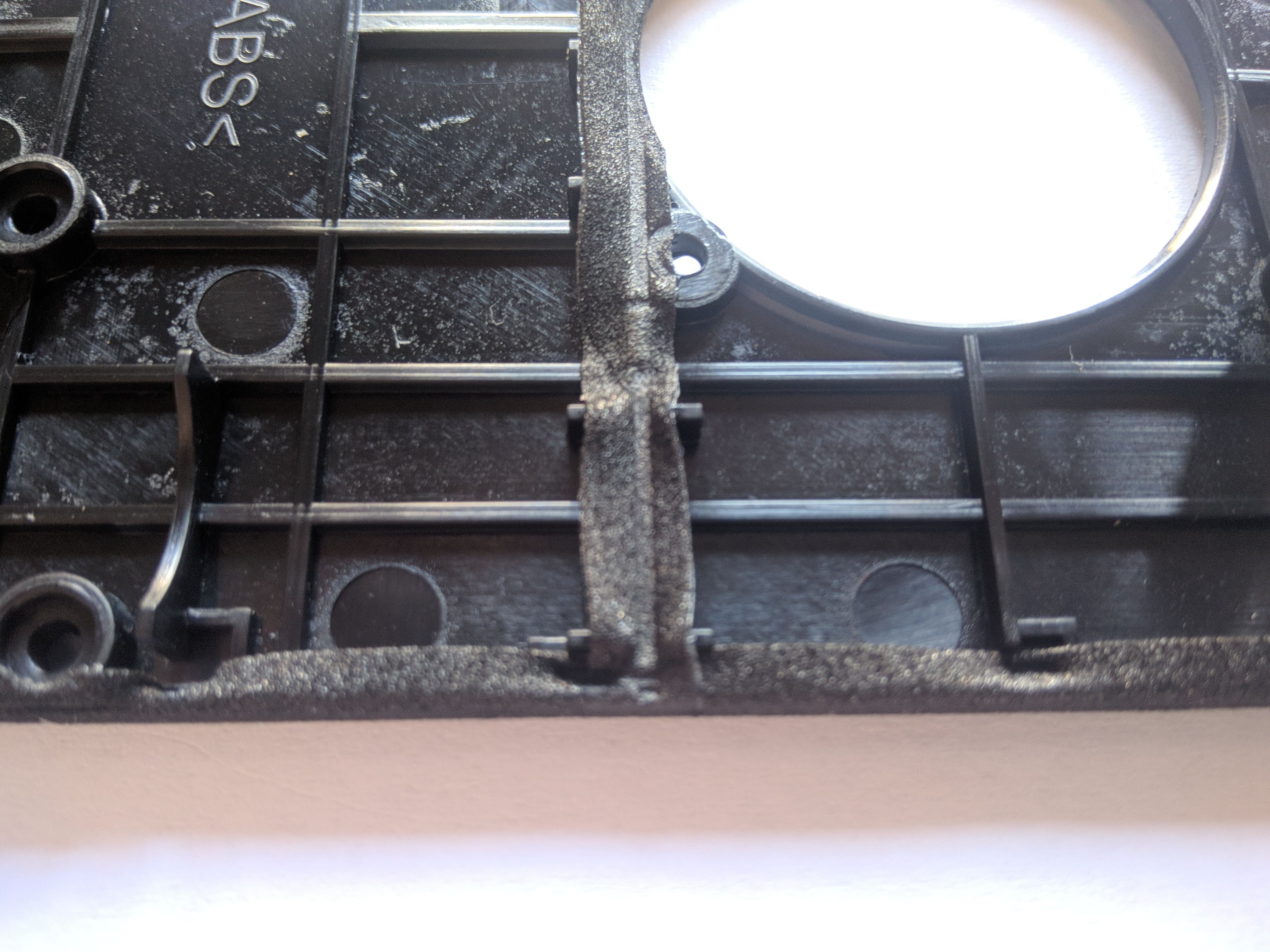
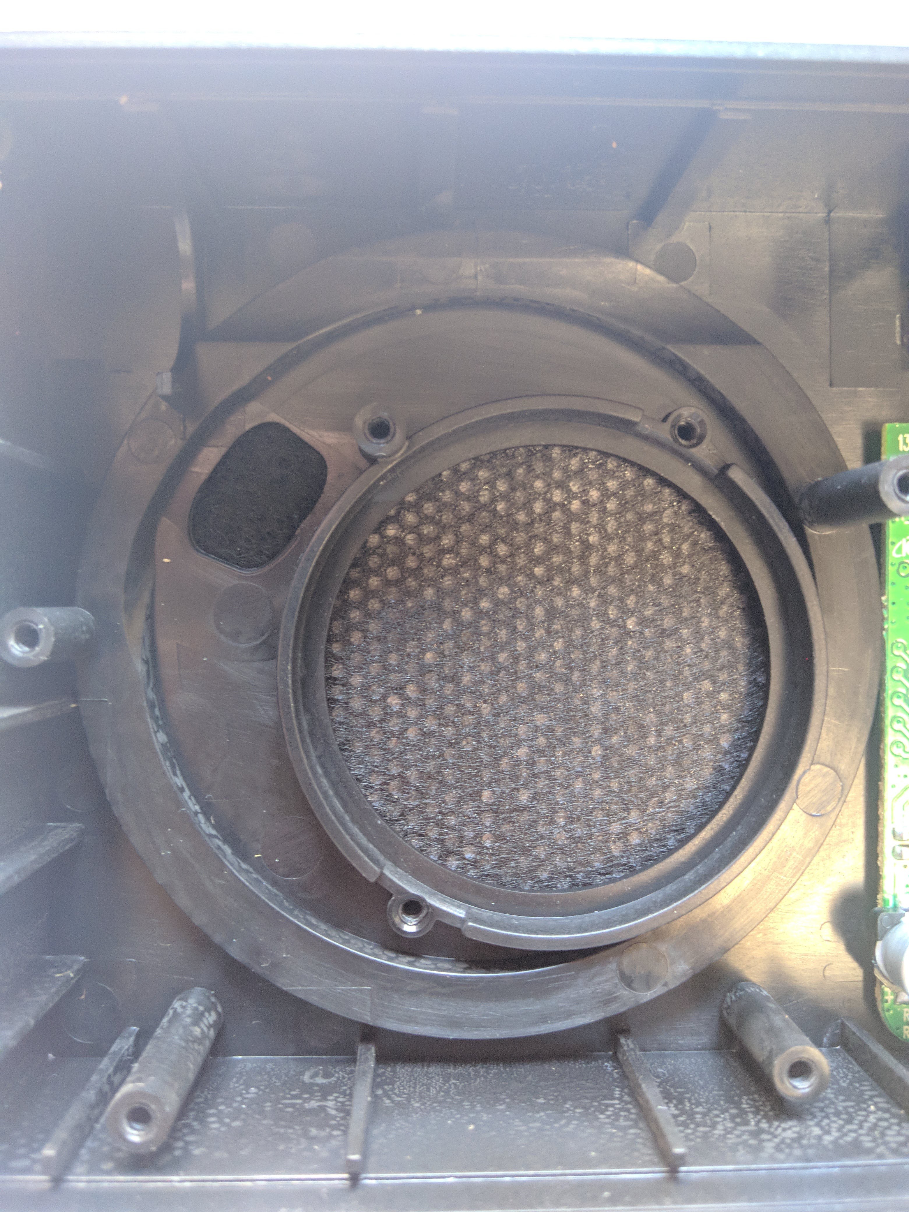
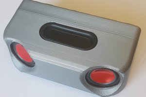
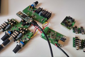
Thoose are all the main parts of the speaker, you will see that it have a bass-reflex design instead of the more common passive woofer type.
There are two PCB, the main one have the class D or AB, the charge circuit and other misc stuff. The other is the BT module.
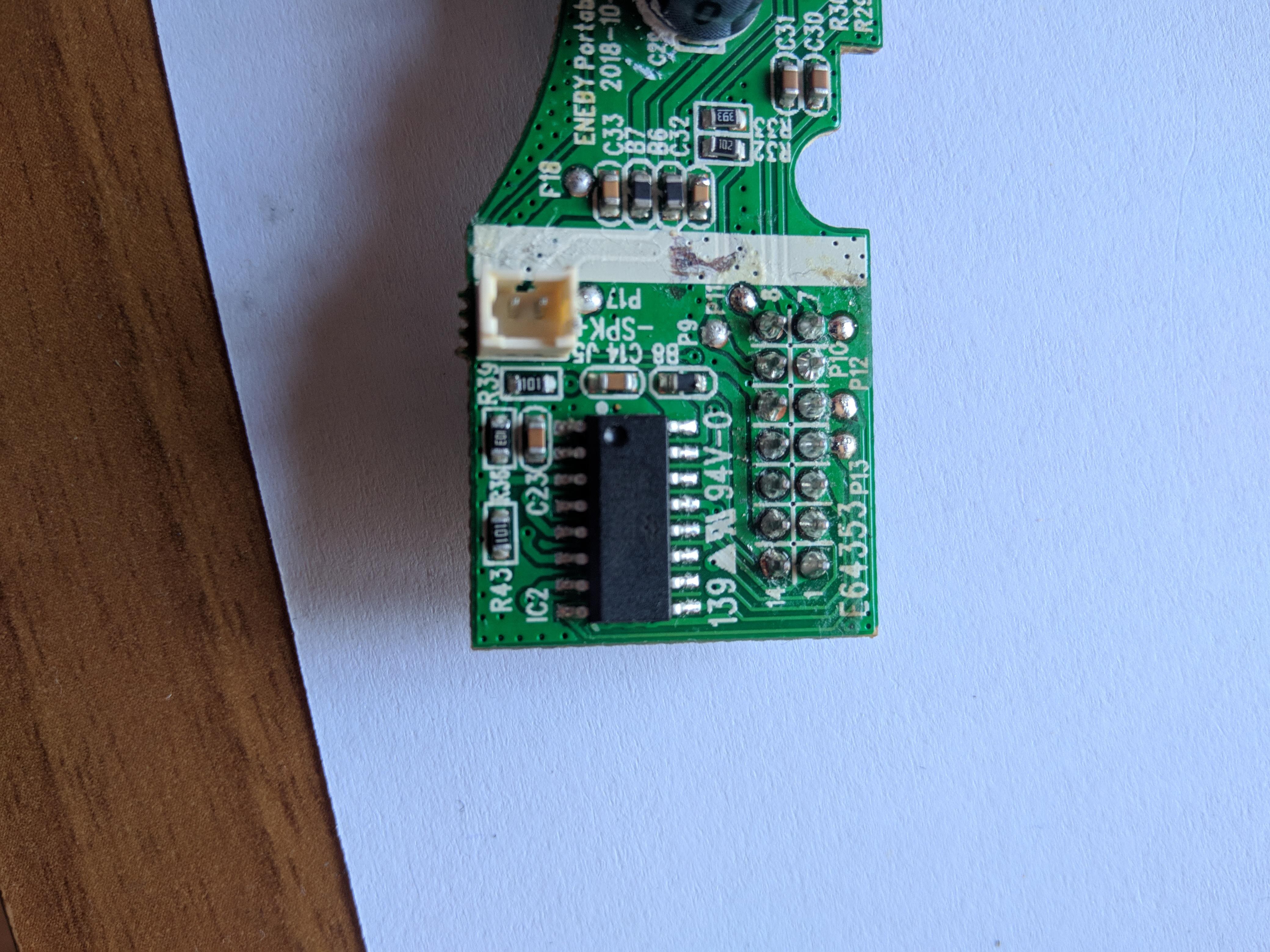
Lets analyze the PCB in more details
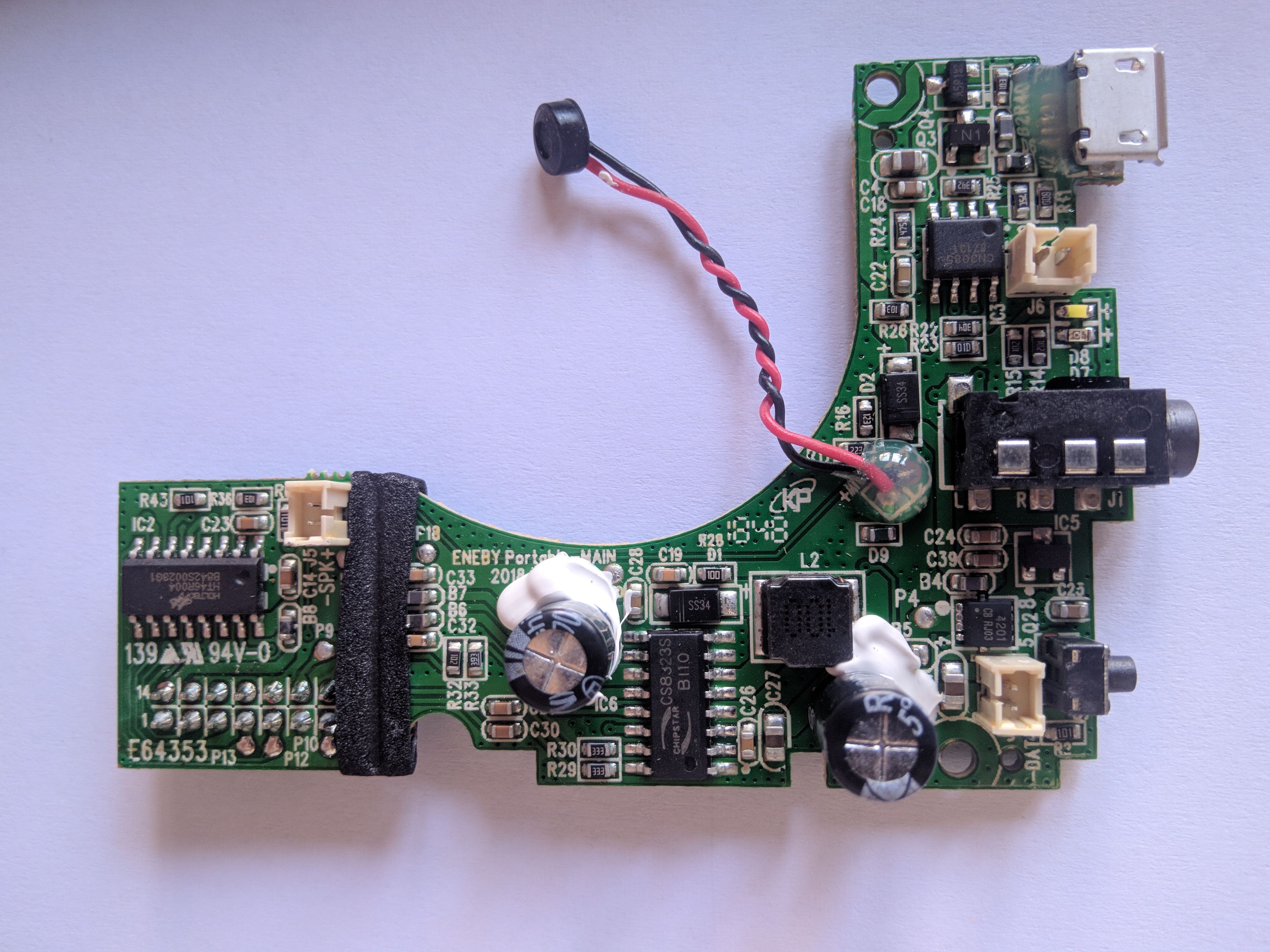
On the right we can see a OTP microcontroller, it just take some inputs and control the status of the BT module via some GPIOs, it also manage the STATUS (White) LED. The BT module can trigger two LED blynk pattern but I cannot find a way to create a real world case for the slow blynk pattern.
They opted for another chip instead of "programming" the CSR8615 built-in LEDs controller. (Please note that the CSR BT chip has a OTP memory for the firmware that is set during manufacturing of the chip itself. The configuration is stored inside a SPI flash)
In the middle we can see the Amplifier the CS8323S it is a hybrid class D and AB amplifier, toggling a pin it can be turned into a different class (it is configured as D-Class) . This chip also have a DC-DC Buck controller in it, it is able to boost the input voltage to a higher value. There are two modes, it is configured to run at 6.5V
The MUTE pin is connected and controlled by the BT module. (There is a voltage divider mady by R32 and R33 even if the)
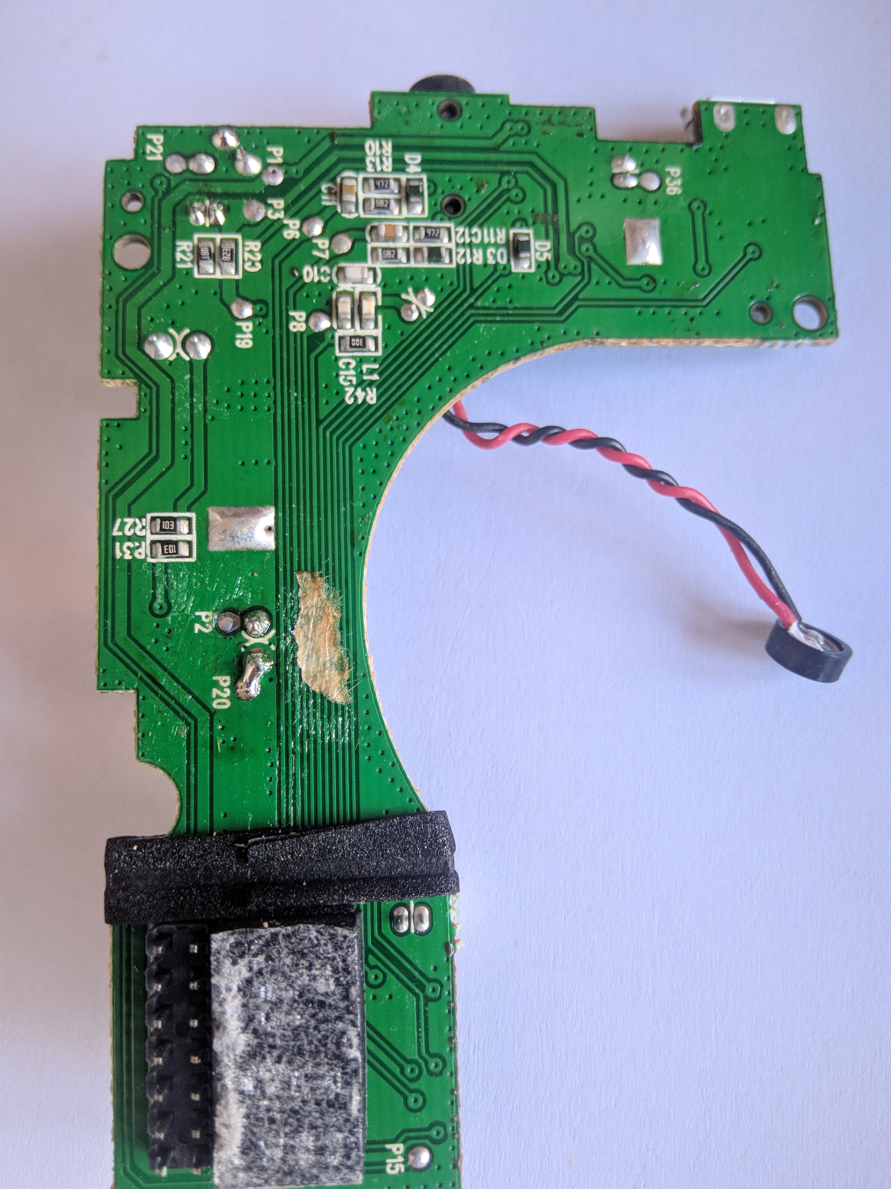
On the top left we can find a standard CN3085 Nickel-Metal Hydride Battery Charger IC, around it there are also some transistors, for now I don't have fully traced the charge circuit. Looks like that is present a Bypass MOSFET to connect directly the USB to the aplifier if the external supply is connected.
The charger have also thermal detection, so a proper NI-MH charge profile is used:
Both the MCU and the BT module runs at 3V3. IC5 is the regulator.
I have spent more time tracing the BT module and the connector between the two boards.
The result is the following diagram:
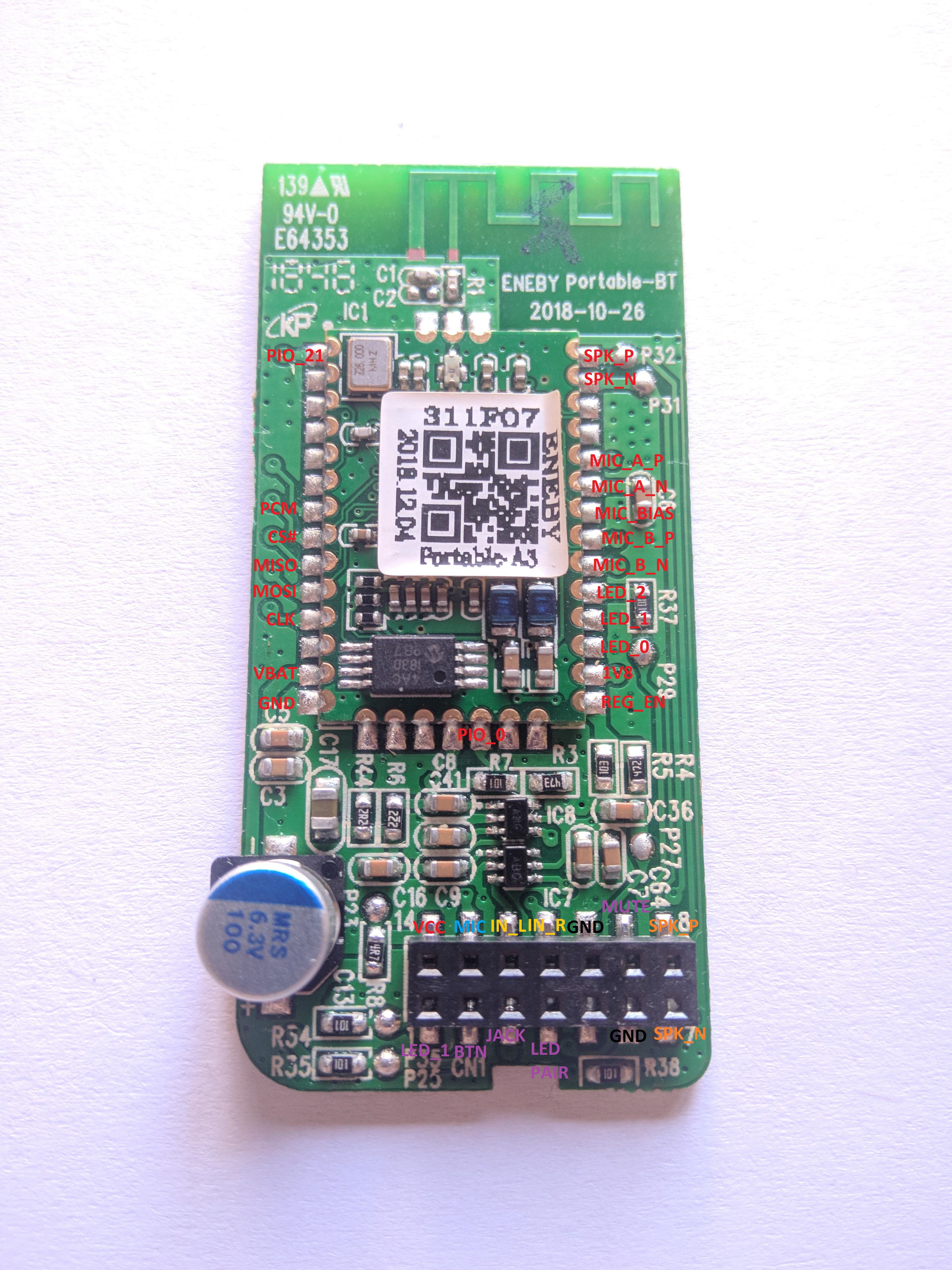
The line input and the MIC input is mixed/muxed somewhere and I still cannot figure out how they made it. IC7 and IC8 are (probably) OP-AMPs.
Unfortunatly after a lot of test and probing I have damaged something, a solder joint or the connector and now I get crappy noisy audio aut of the speaker.
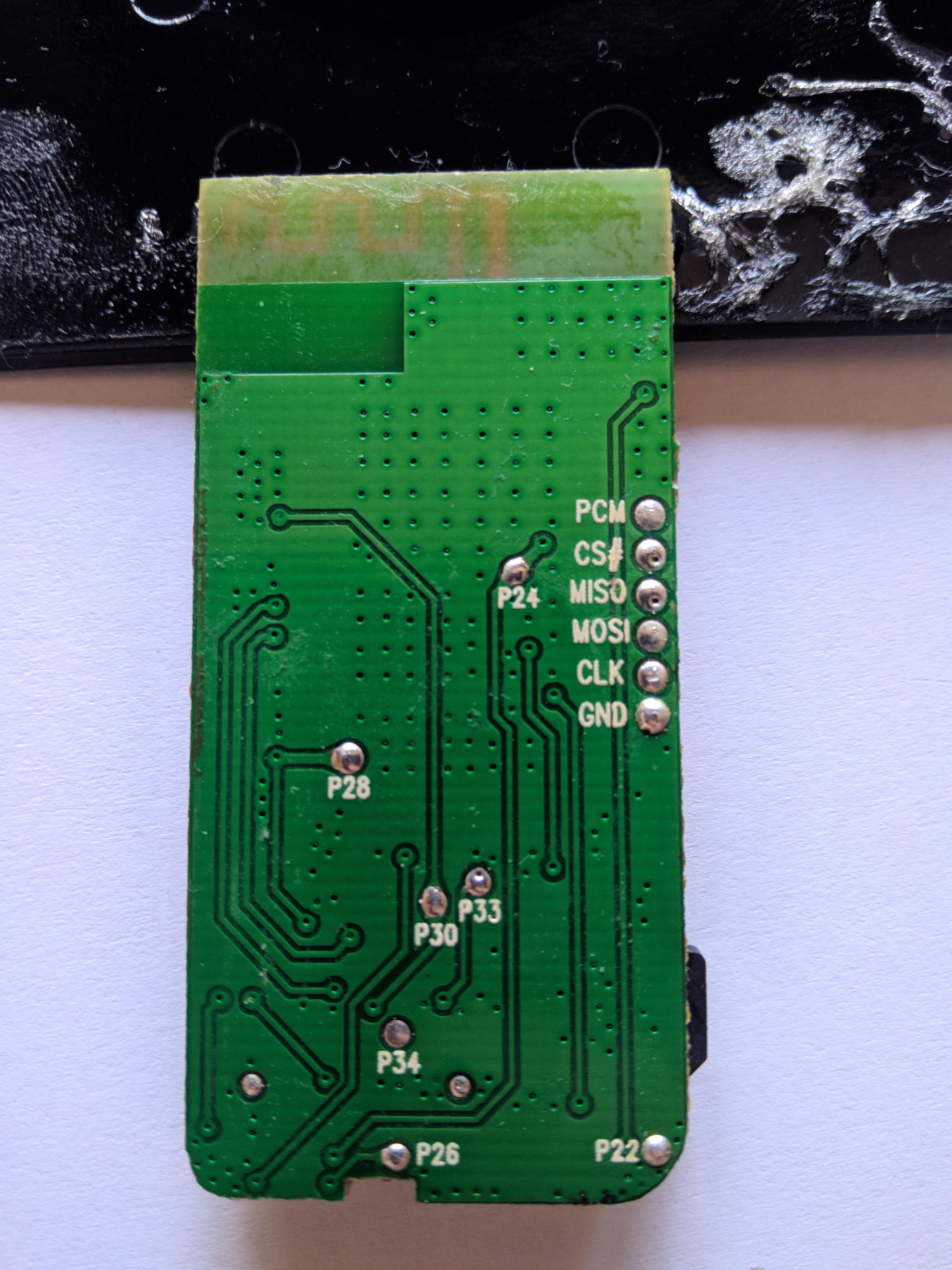
The interesting part is the fact that both the BT module and the amplifier board have a lot of test point to hack into:
My initial idea was to modify the charge circuit to add a lipo/lion battery but the hole in the middle used by the stand make quite hard to find a god suitable battery.
More study is needed!
Useful links & Datasheets:
CS8323S http://www.chipstar-ic.com/UploadFiles/pro/CS8323S_ch_v1.1.pdf
CN3085 http://www.consonance-elec.com/pdf/datasheet/DSE-CN3085.pdf
CSR8615 https://www.datasheetq.com/datasheet-download/841989/1/ETC/CSR8615
 Michele Perla
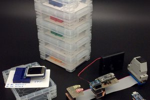
 William
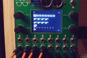
Seemingly the equalizer can be reprogrammed using a software tool PSTools. One can either edit the content of the EEPROM, or program the EEPROM through SPI programmer connected to the bluetooth PCB. Unfortunately the Chinese clone of the CSR USB-SPI interface costs around the same as the Eneby Portable. Add the effort of learning the tool and I scratched the idea.
https://www.eevblog.com/forum/projects/programming-off-the-shelf-csr8635-module/75/
It is not trivial to make such a small speaker work over lower frequency ranges. The tiny speaker has a relatively high self resonance, which may to some extent be lowered by the bass reflex. Below the resonant frequency, the speaker has a very low efficiency, therefore one has to amplify the low frequencies excessively, thus one has to ensure that the speaker coil is not overheated likely using banded automatic volume control. In addition, one has to control the amplification around the speaker resonant frequency carefully, otherwise the speaker may get destroyed by excessive membrane excursion. Also at strong resonance, the speaker membrane excursion is excessive and the speaker is no more linear.
I believe what happened here is that the Eneby Portable designers decided to accentuate the basses. Everybody loves basses indeed. But instead of suppressing the speaker resonances, they actually made the speaker resonance worse by setting the knee of the low pass filter too high. Maybe the bluetooth chip cannot do better, I don't know.
The problem number two is, that the YouTube videos I tested the speaker with are often processed to accentuate lows and highs while suppressing mids. That may be fine when playing on a poor speaker or a smartphone, however the Eneby implements the same of audio processing, doubling the basses. When playing a flat record on the Eneby, the basses are somehow less offending, though still leading to some speaker resonances leading to audio distortion.
As my smartphone does not provide any way to equalize audio when playing YouTube videos, and I bought the Eneby to listen to speeches, I just connected 10uF non polarized aluminum capacitor in series with the speaker to suppress the bass response. With this capacitor value, some high bass recordings still produce quite offensive bass resonances, but most speech recordings are passable. The capacitor made the difference for me between thrashing the unit and keeping it.