 Jacob Killelea
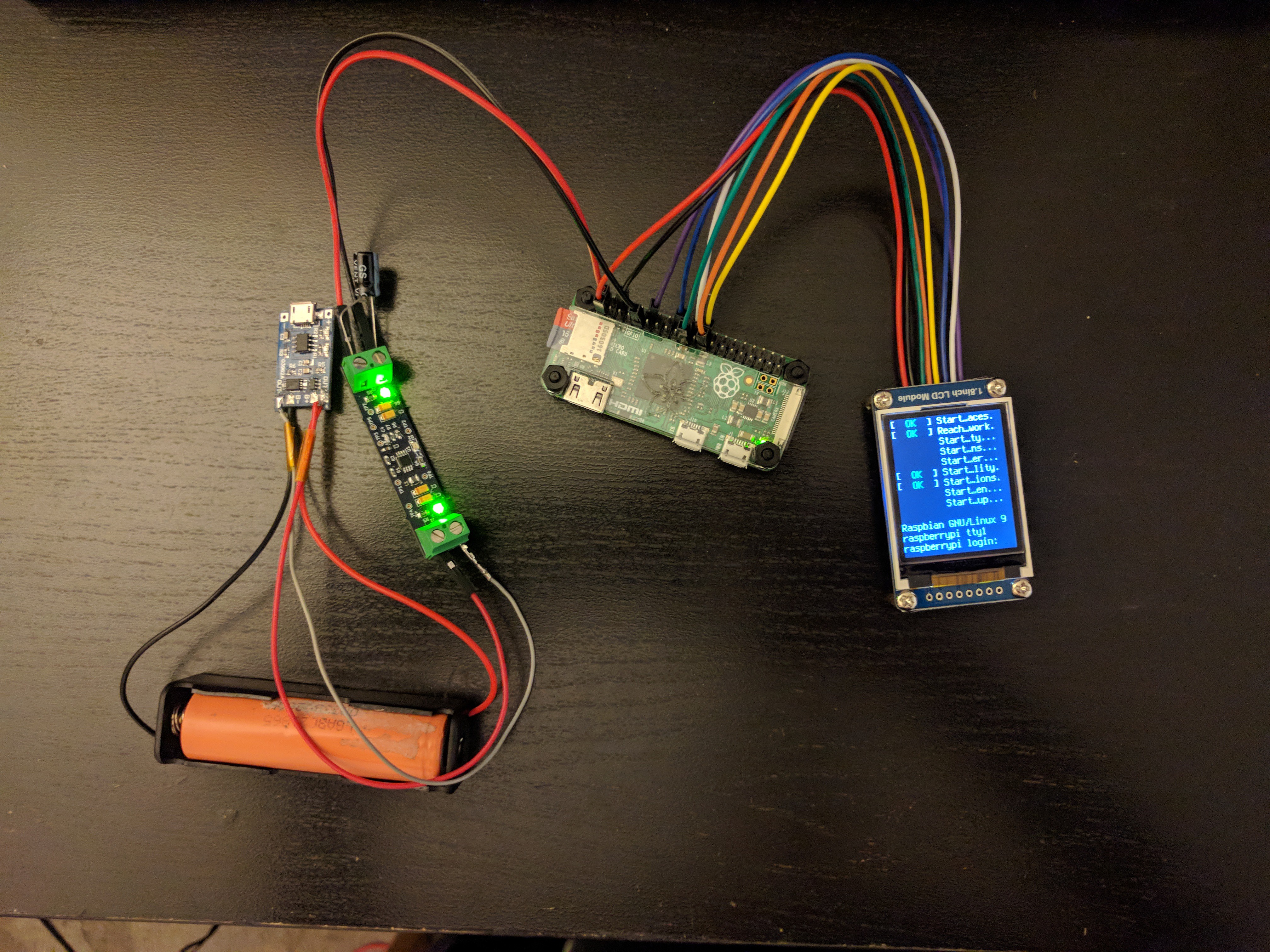
This is is the general setup for the battery system. I switched ICs, and I'm using the NCP1421 from ON Semi. It's tiny, and this was my first time working with 0603 caps and resistors, but things turned out great once I had all the connections solid. I used longer wires from the battery IC the first few times and it caused problems with peak current draw somehow. Anyways, it's great to see it booted! The screen is an ST7735 based LCD, and I had no idea it had kernel modules already available until after I bought it. It's pretty funny to see the boot messages so truncated.
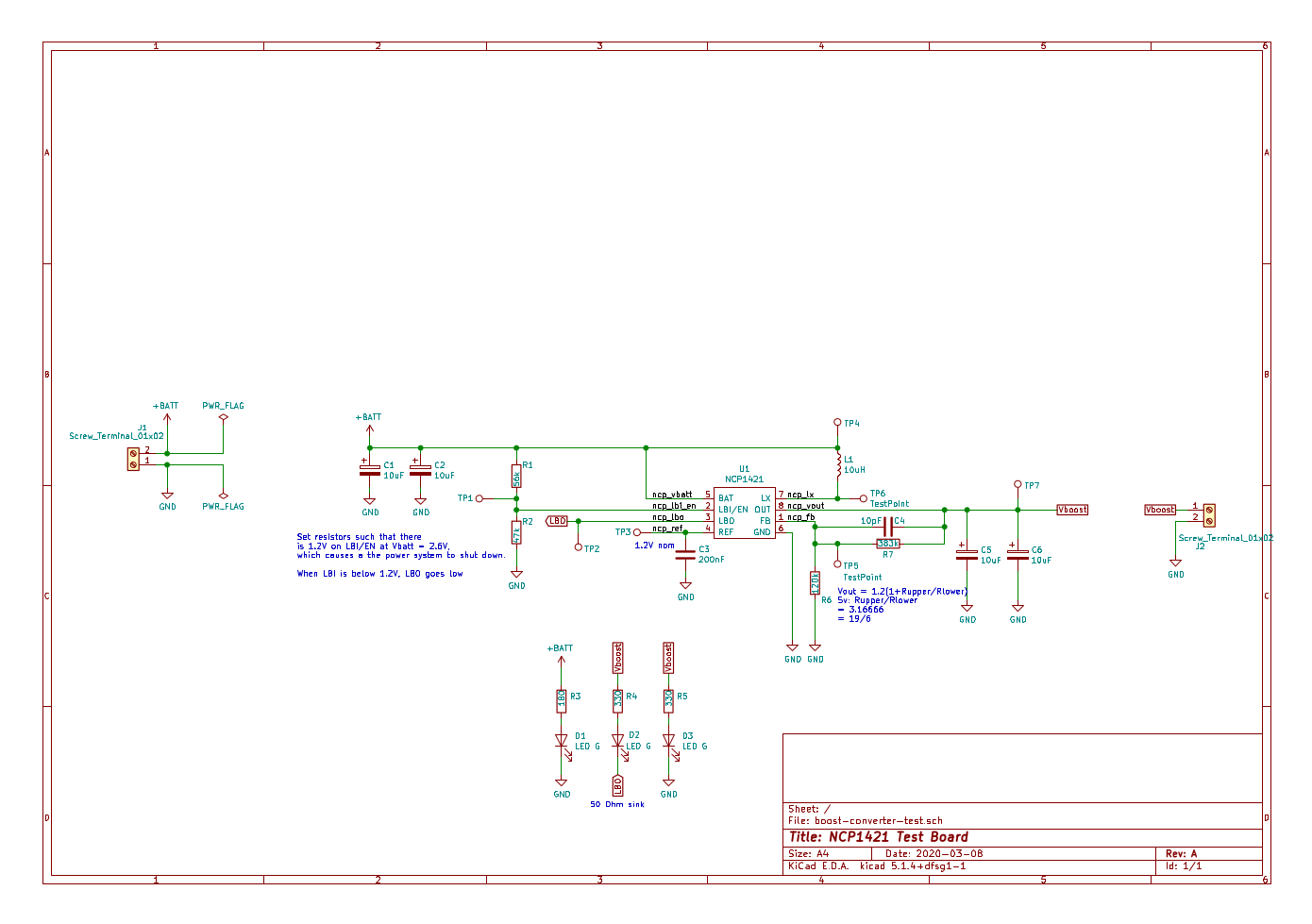
Here's the schematic of the voltage booster board. I'm liking this chip a lot and it'll almost certainly make it into the final design.
The next step is going to be to get everything put together onto a breadboard so that I can start integrating it with the software, and maybe 3d print a case.
Discussions
Become a Hackaday.io Member
Create an account to leave a comment. Already have an account? Log In.