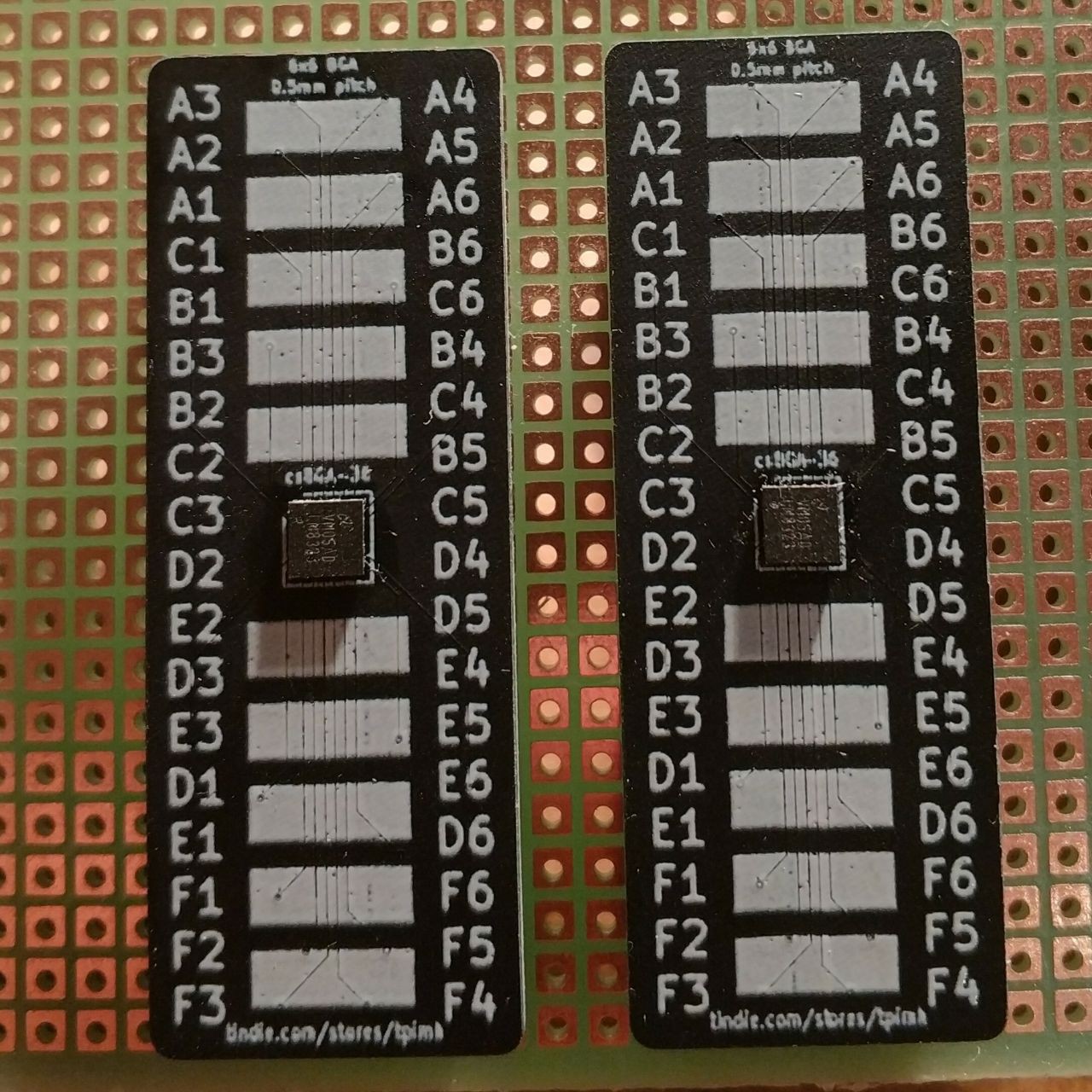
A while ago I designed and ordered csBGA-36 breakout boards. The designs for the boards can be found in my GitHub. The board is designed with 0.0762mm/0.0762mm trace width/clearance and 0.2mm/0.15mm via diameter/drill in order to make each pad of 6×6 0.5mm pitch BGA easily accessible on a 2.54mm pitch breadboard. This was my first attempt in designing and soldering BGA PCB. I soldered LM8323 using hot air. One of the two assembled boards passed testing for continuity and resistance between pads, the other needs rework. After connecting it to 1.8V power source, it turned out it consumes 8µA in standby and 1.9mA with reset connected to ground. According to datasheet, these values are healthy for this controller, so it should be functional. Next step will be interfacing it with a computer using I²C protocol (luckily, Linux driver already exists).
 Twisted Pair in my Hair
Discussions
Become a Hackaday.io Member
Create an account to leave a comment. Already have an account? Log In.