It is Paul Stoffregen's fantastic Audio Library that drove the choice of the Teensy 3.2 for control. I had seen his DTMF decoder example and I knew that it should be able to easily generate the tones for the phone using the library's sine-wave generators. I figured the rest of the logic would be well within the capabilities of the Teensy and it is. The built-in ADC and DAC signals can be used so there is no need for an external codec.

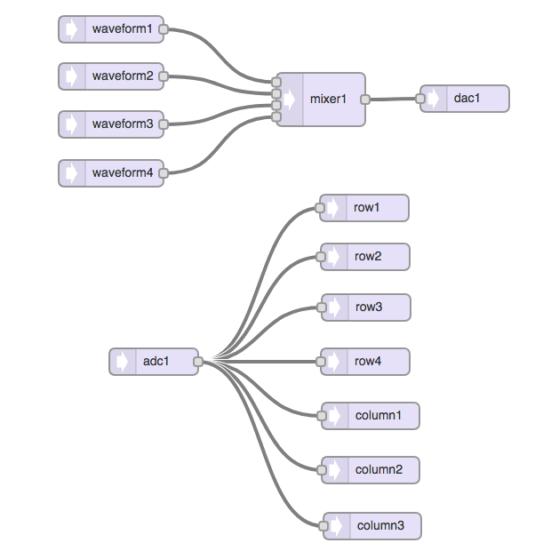
The system is comprised of two independently operating halves. An output stage combines up to 4 waveforms and an input stage uses seven tone decoders to detect the DTMF tone pairs (the cross between row and column decoders indicates which button has been pressed).
The system currently generates three output tones using 2 or 4 of the waveform generators.
| Tone | Freq 1 | Freq 2 | Freq 3 | Freq 4 |
| Dial Tone | 350 Hz | 440 Hz | - | - |
| No Service | 480 Hz | 620 Hz | - | - |
| Off Hook | 1400 Hz | 2060 Hz | 2450 Hz | 2600 Hz |
The No Service tone (pulsed) is used to indicate there is no Bluetooth connection when the user picks up the receiver. The Off Hook tone (pulsed) is used to indicate the receiver has been left off-hook for more than 60 seconds. The Bellcore standards specified power levels for each tone but my system makes no attempt to match these. It drives the maximum level out of the Teensy that was sufficient to drive the input of the AG1171.
The DTMF decoder is straight from the Audio Library example with an approximately 30 mSec detection window for each of the seven frequencies. DTMF was designed to be an in-band signaling technology, meaning that the tones travelled along with the rest of the audio. In fact there is an interesting history to read. DTMF is still used today in various other signaling systems.
I found one bug (at least on my old version of the library that I currently have loaded). The PJRC Node Red Audio Editing tool generated code that put the DAC object instantiations first followed by the ADC objects. The ADC didn't work until I reordered the object instantiation with the ADC side first.
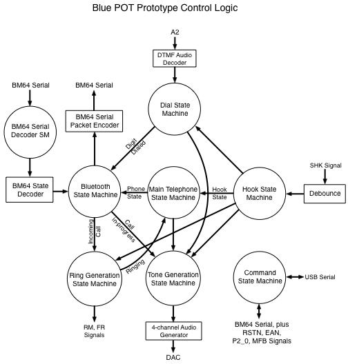
The system is controlled through a set of interlocking state machines. This architecture works very well although it essentially came into being because I was slowly gaining experience by building one function at a time. State machines share state and events as necessary but only perform one function. The telephone-related state machines evaluate every 10 mSec (primarily for debouncing the switchhook signal). The Bluetooth state machine evaluates every 20 mSec. The Command state machine evaluates as serial data arrives from the host.

The Bluetooth State Machine is the system master and coordinates between the Bluetooth side and the telephone side.
 Dan Julio
Discussions
Become a Hackaday.io Member
Create an account to leave a comment. Already have an account? Log In.