 kodera2t
By using the embedded power supply, we can also measure active circuit without additional power supply.
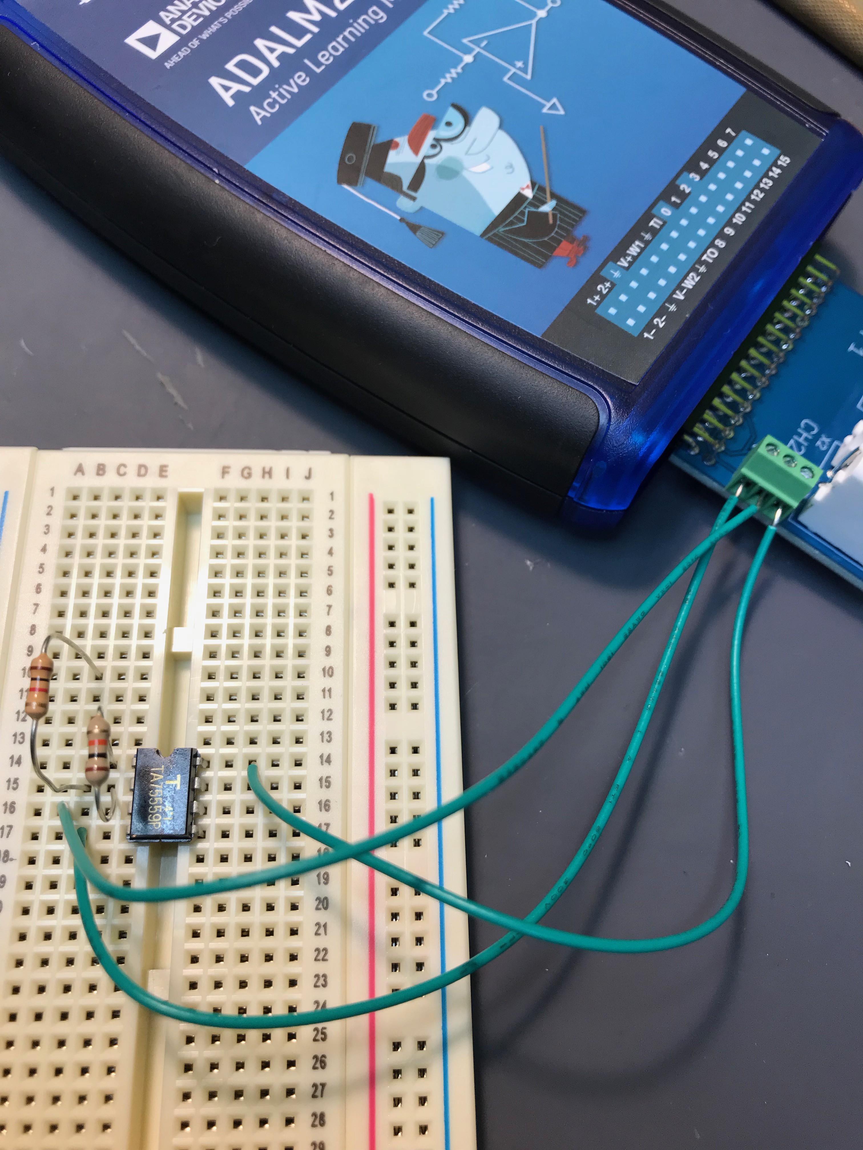
My adaptor has power supply pinout and let's connect V+, V- and GND to a... for example inverting amplifier.
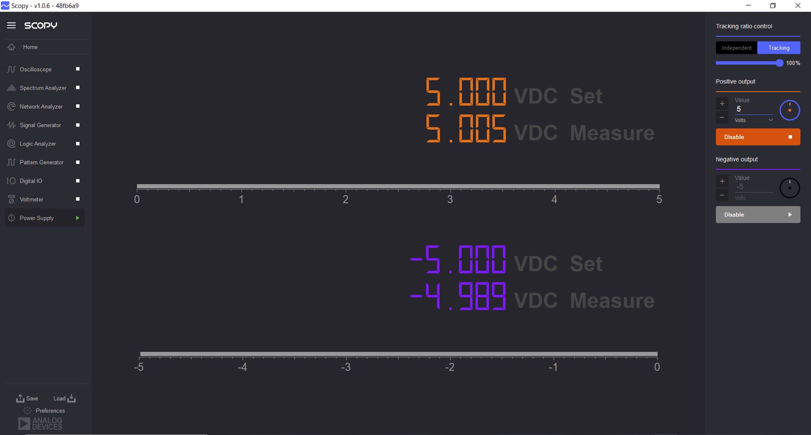
The output voltage can be set on Scopy. This time it is for op-amp power supply so let's make it "tracking" mode and set maximum voltage, 5V and push "Enable" to activate power supply.
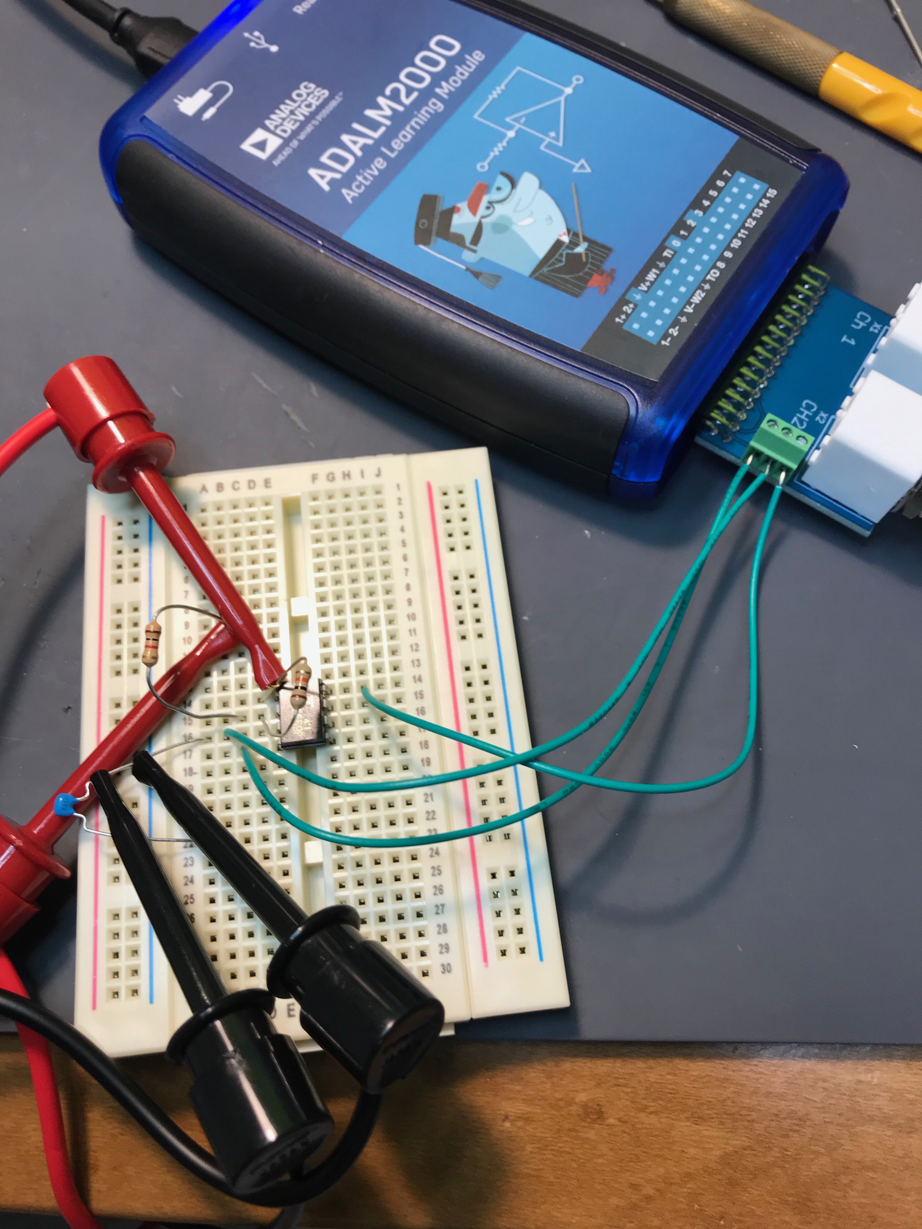
Now two BNC terminals can be connected to input and output of the circuit. Two GND clip are internally connected in the adaptor, but connect just to make it sure. (The frequency range is not so strict, but it is good habit to connect always.)
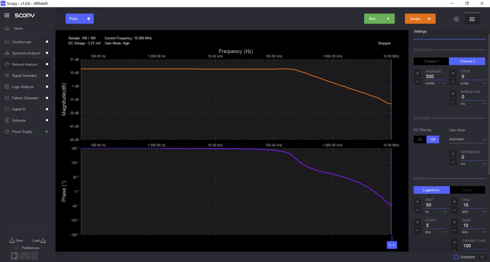
The gain and phase response will be available after setting
(1) Reference to Channel 2
(2) signal level 500 mV
(3) measurement frequency range from 50 Hz to 10MHz.
As we can see in the result, this op-amp works perfectly under 100 KHz. Above around 200 kHz, both phase and amplitude are getting imperfect response.
Discussions
Become a Hackaday.io Member
Create an account to leave a comment. Already have an account? Log In.