 aloismbutura
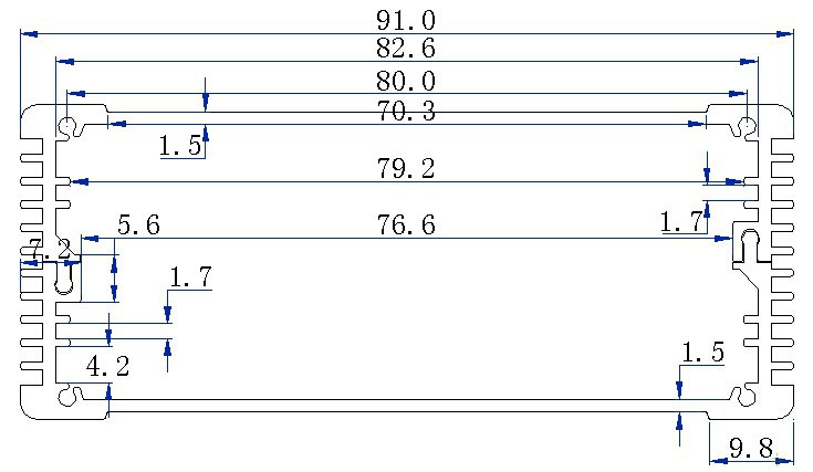
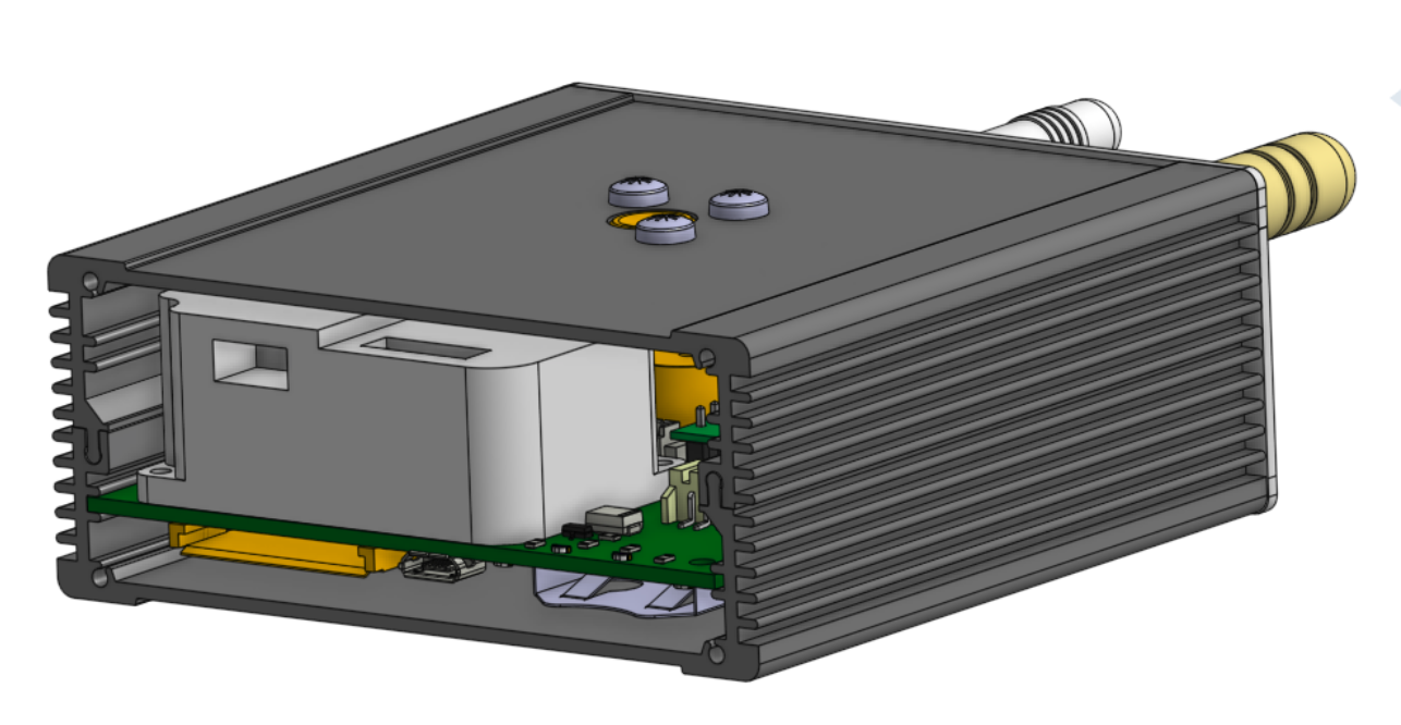
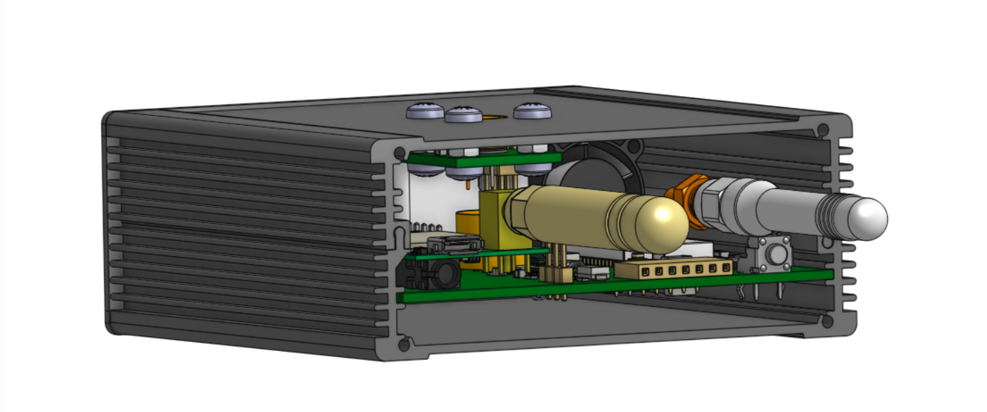
We obtained the following aluminum profile(Code REH8253) from a chinese manufacturer www.robustcasing.com:
Due to the sliding action and play within the enclosure, the copper was pulled back from the board edge to accommodate this movement.
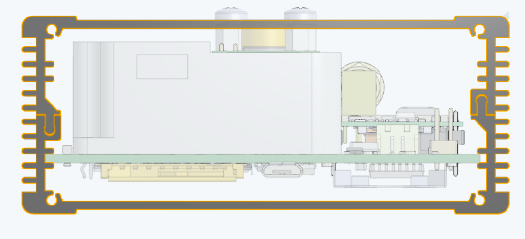
PCB with copper pulled back
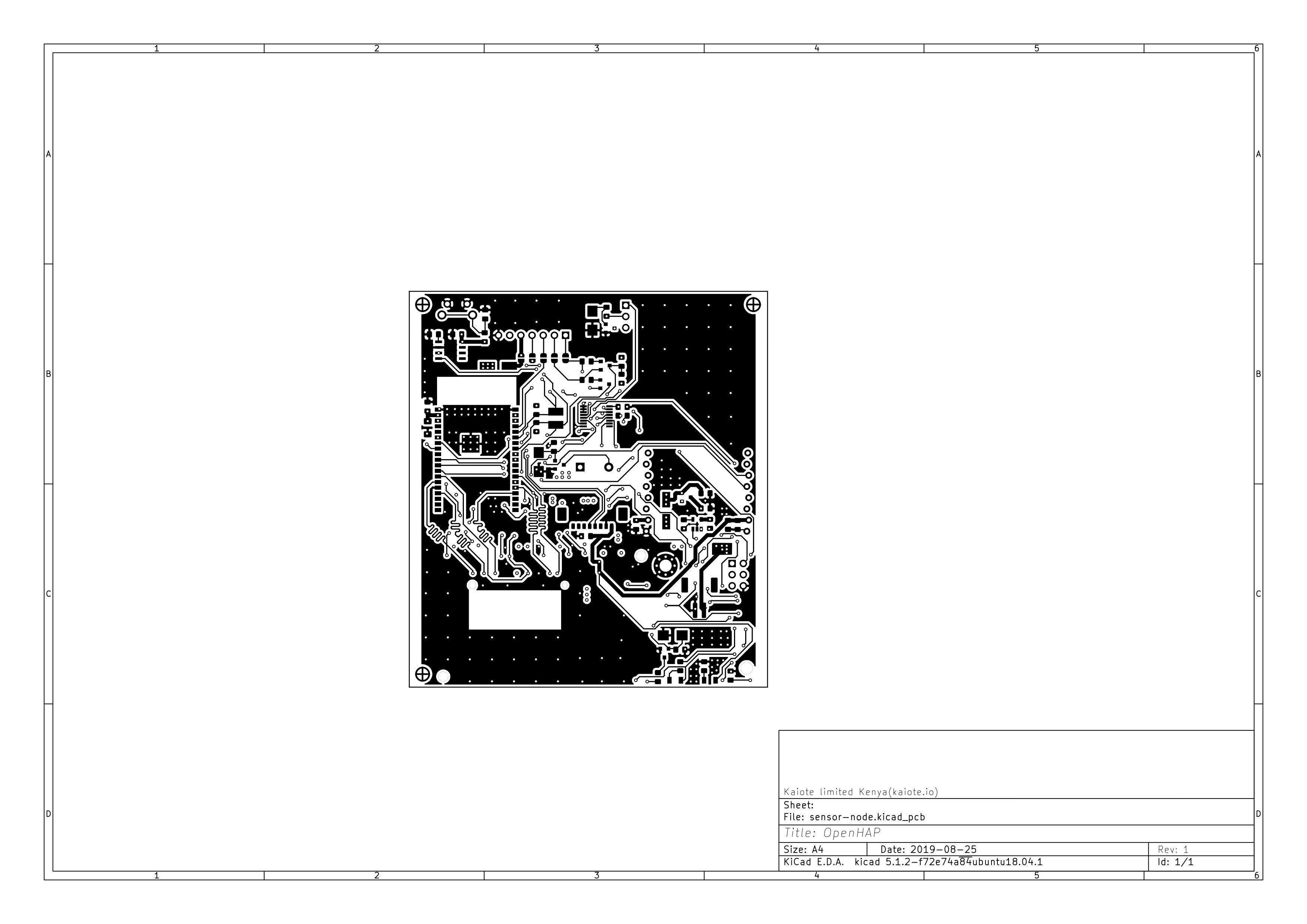
Front side
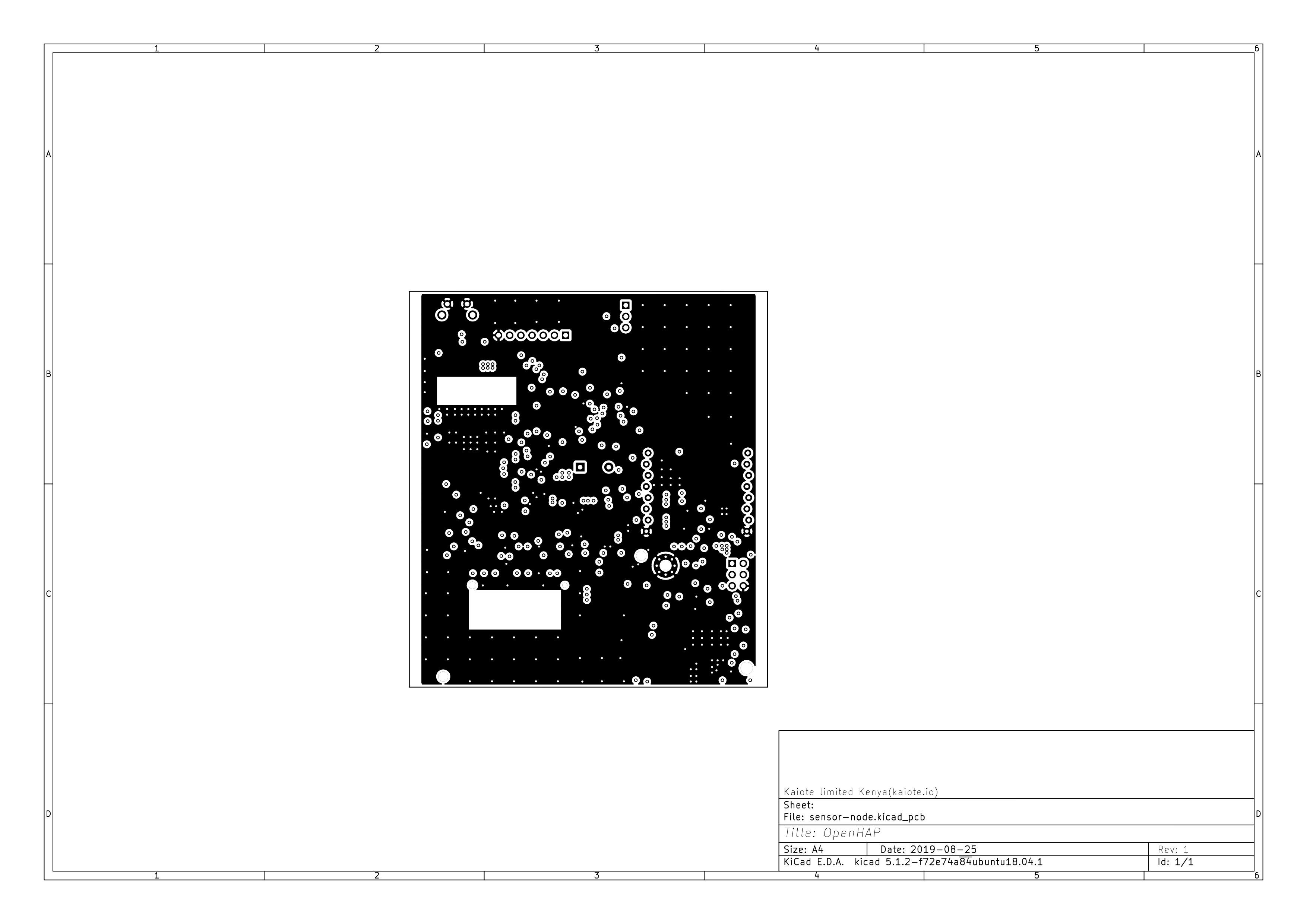
Back side
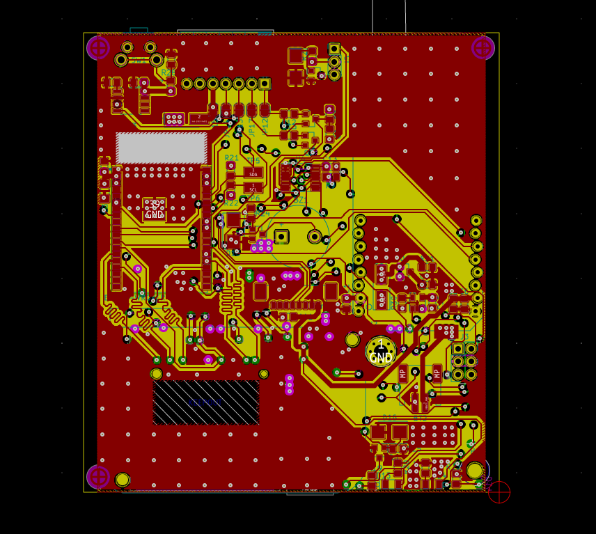
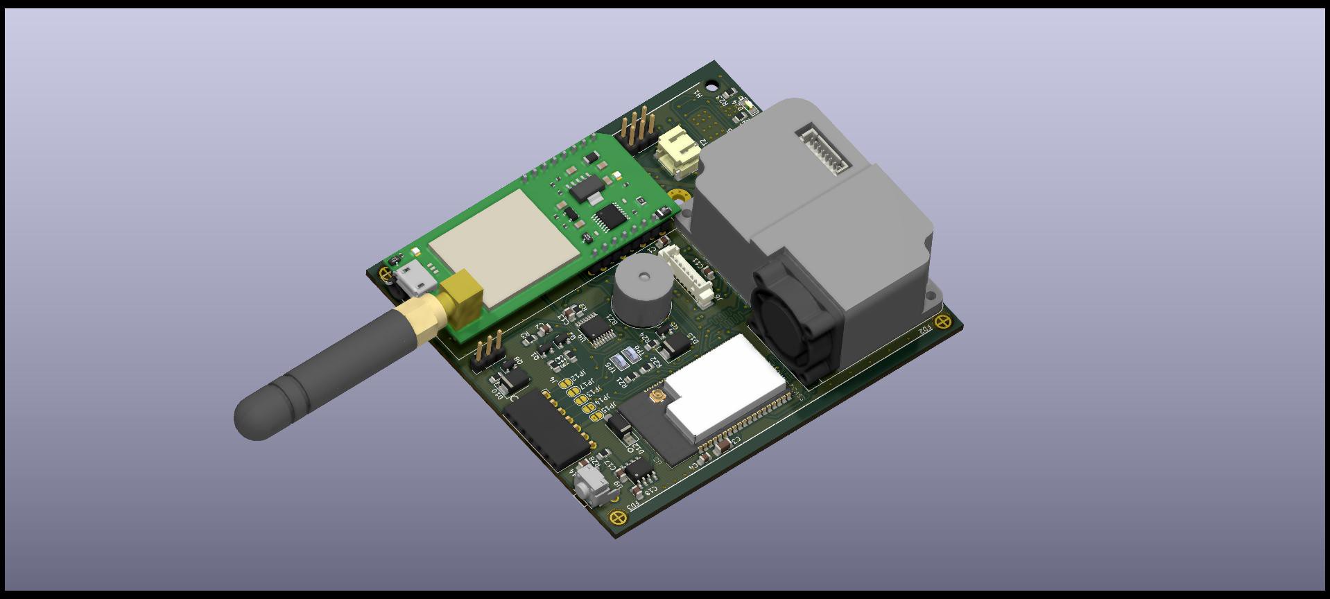
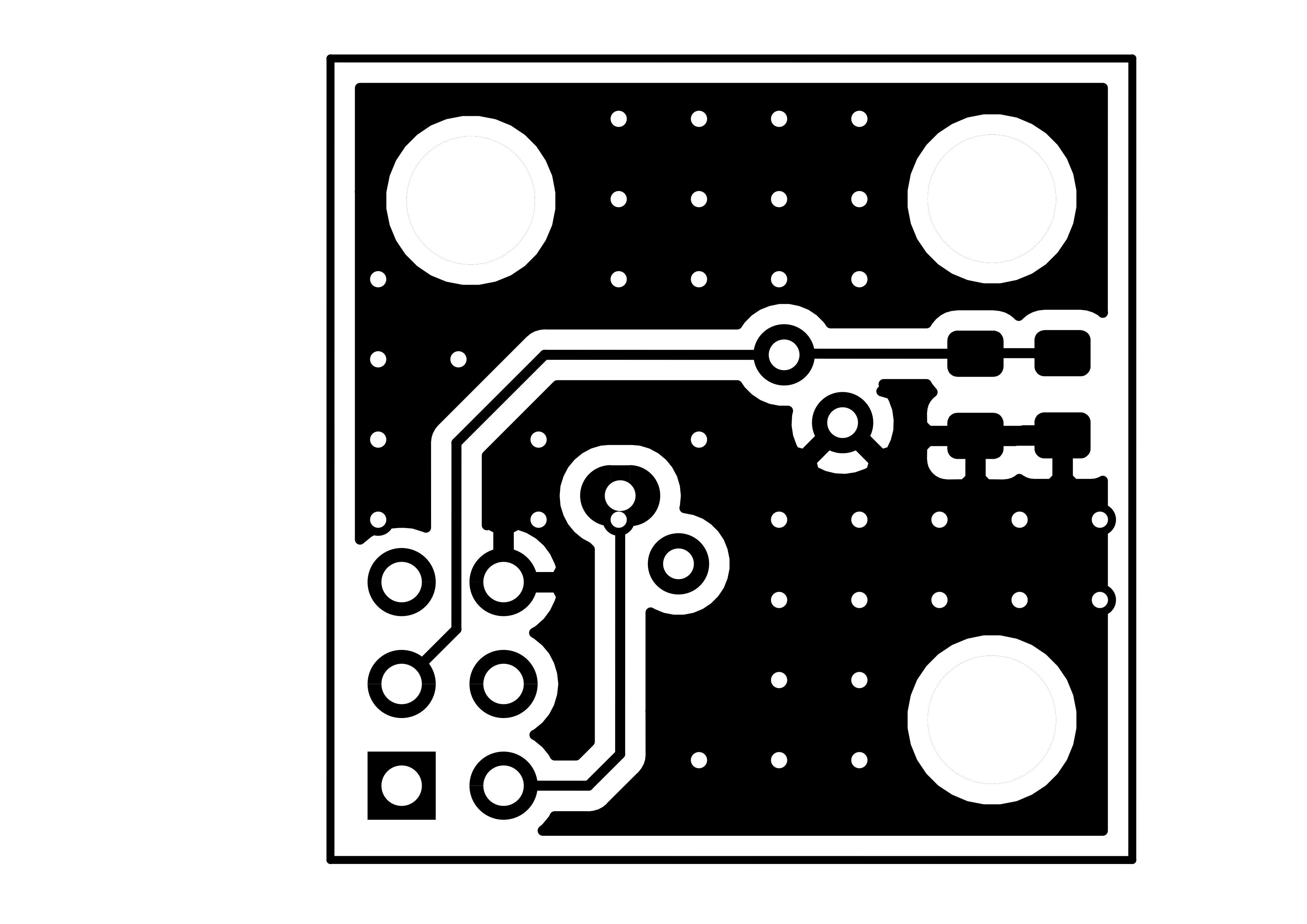
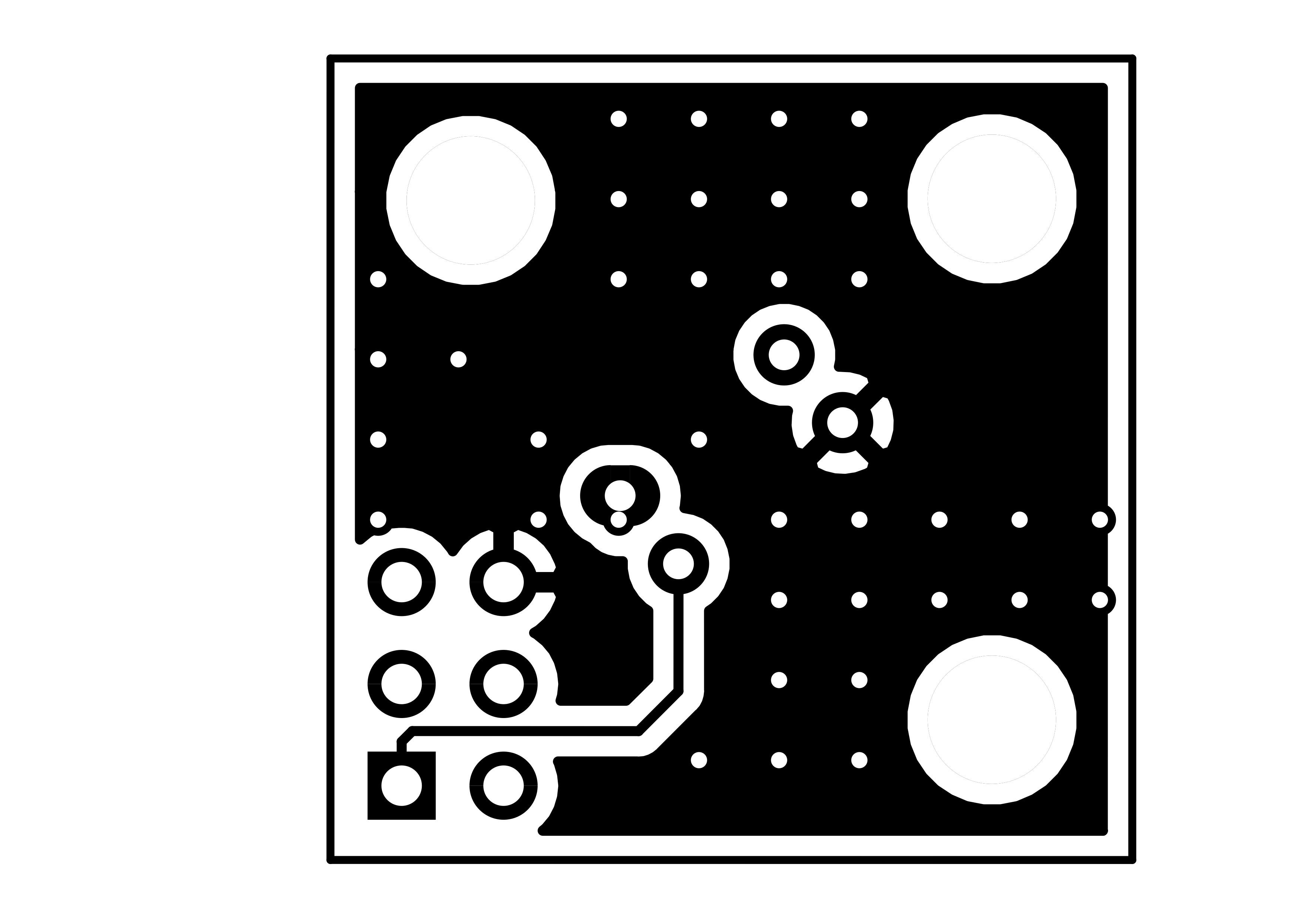
PCB layout on 4 layer board.
Board specifications: 4 layer FR4 1.6mm thickness, ROHS, 1/1oz, ENIG surface finish, Green Solder Mask, White silkscreen legend color.
Top layer

Inner layer 2
Inner layer 3
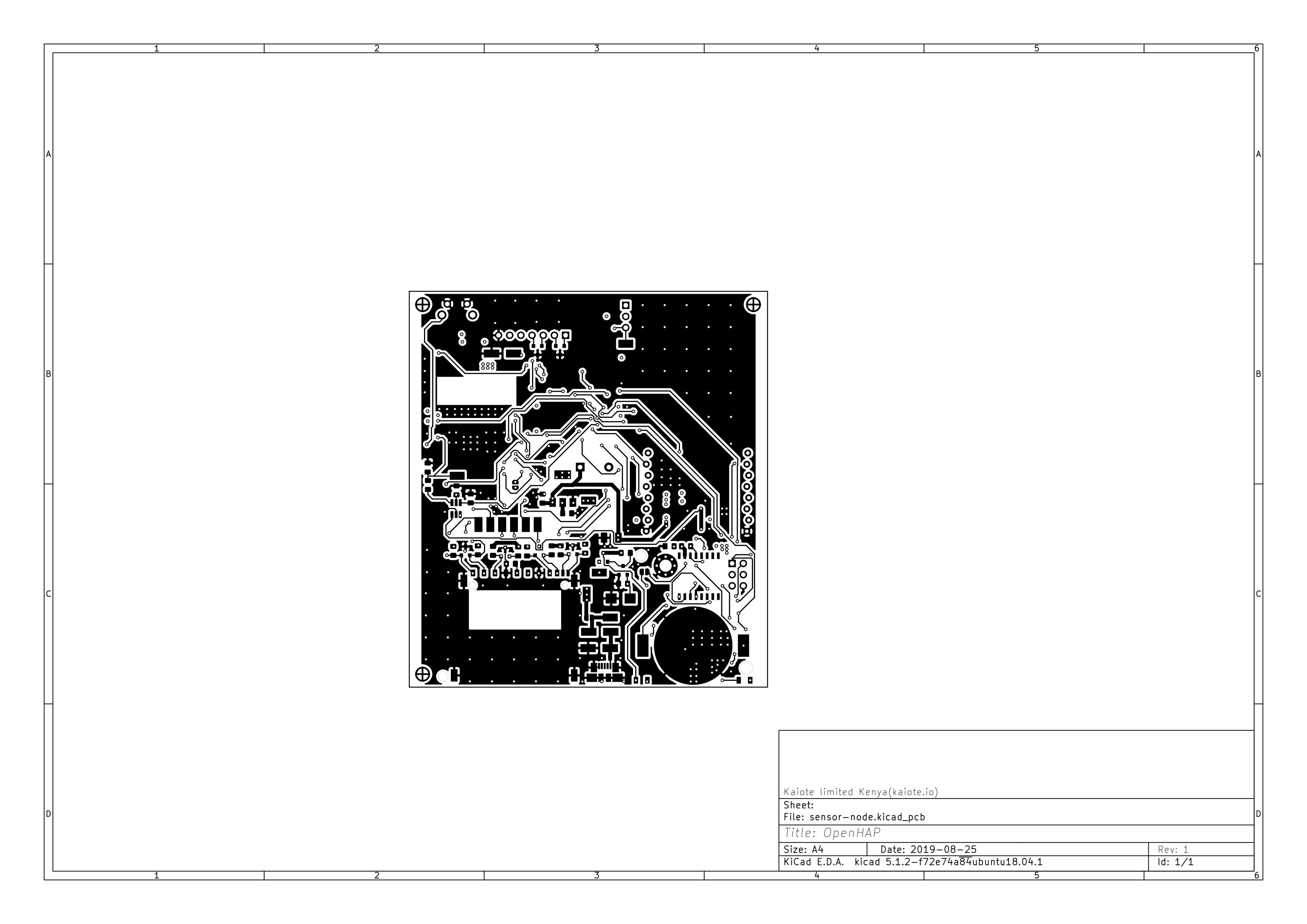
Bottom layer
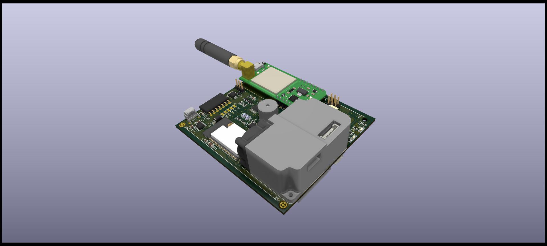
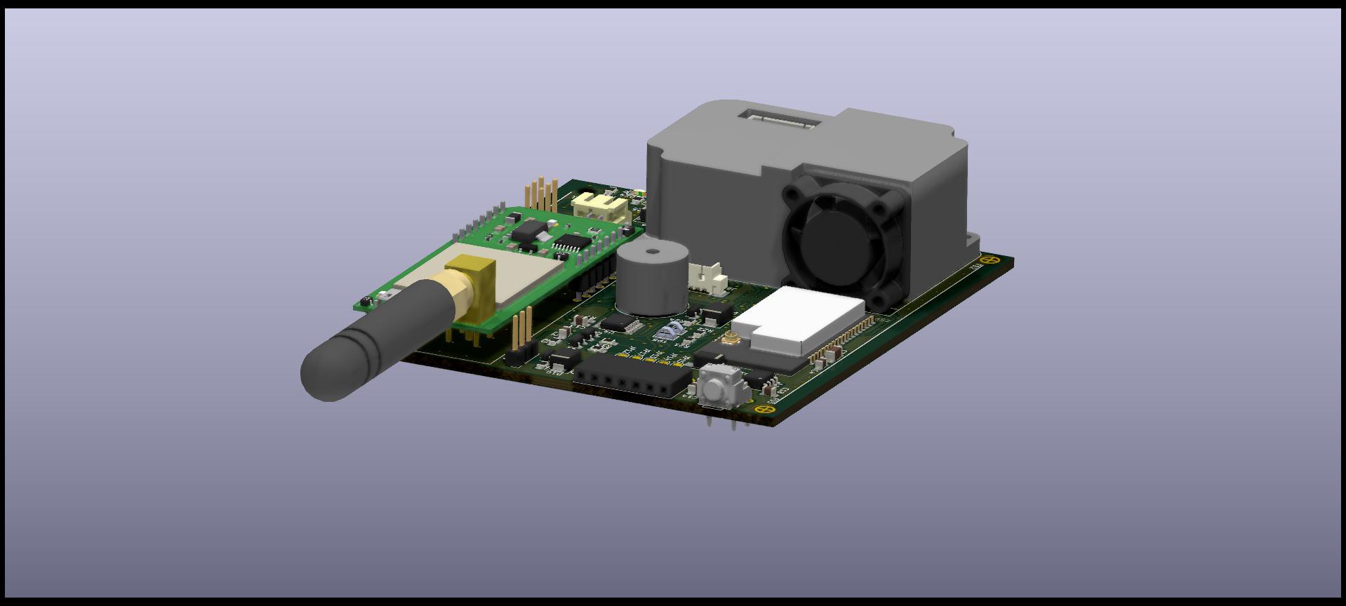
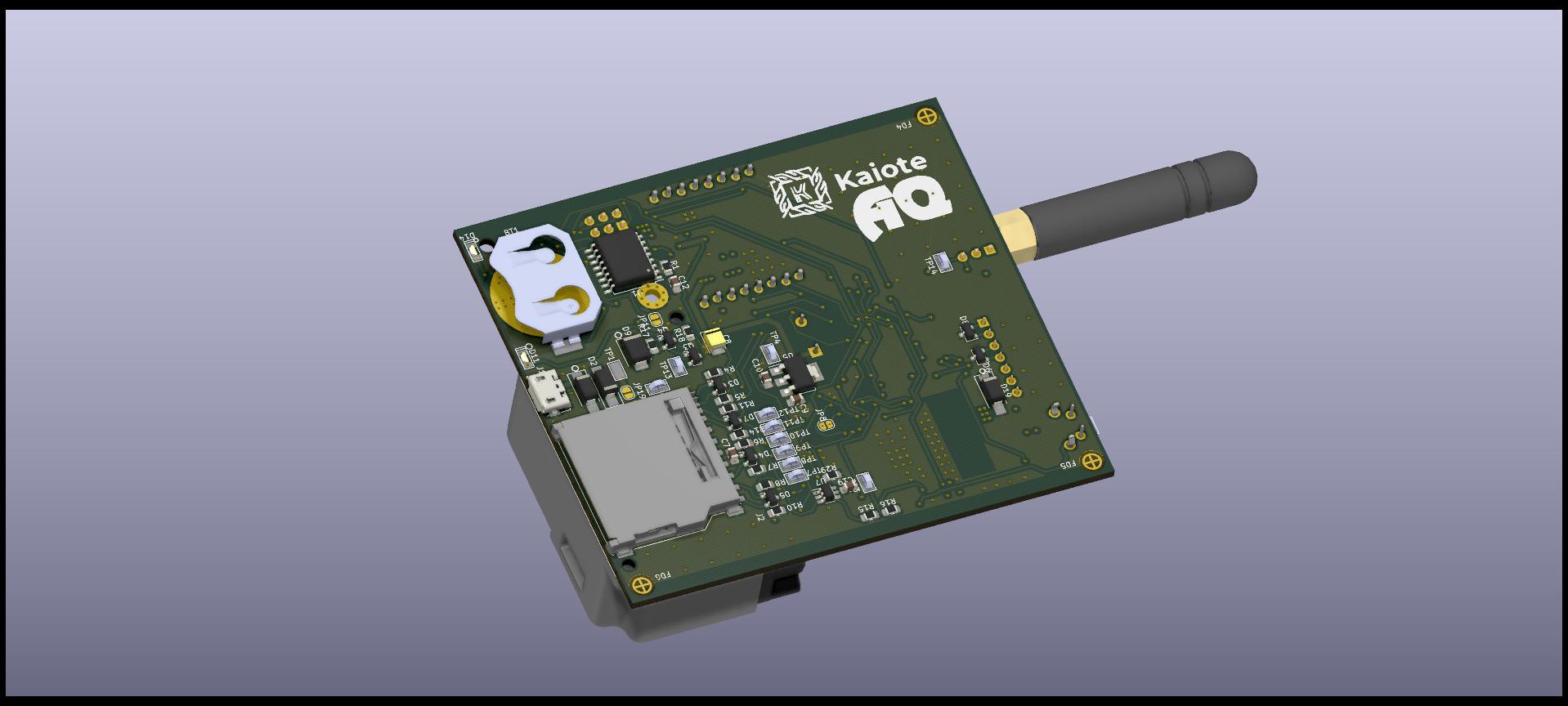
3D rendered PCB views right from Kicad
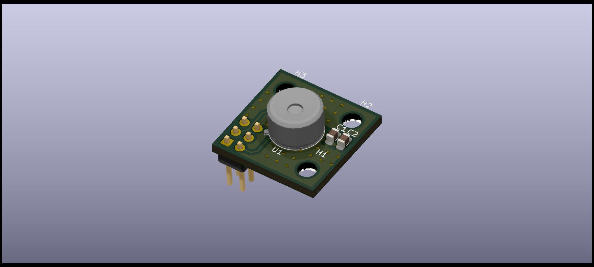
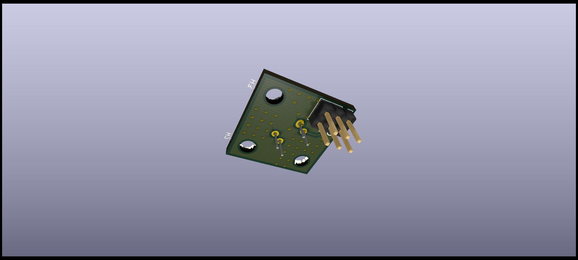
With regard to the 2D thermal array sensor add on:
Board specifications: 2 layer FR4 1.6mm , ROHS, 1/1oz, HASL surface finish, Green Solder Mask, White silkscreen legend color.
Top layer
Bottom layer
3D rendered PCB views right from Kicad
Discussions
Become a Hackaday.io Member
Create an account to leave a comment. Already have an account? Log In.