 Adam Taylor
Introduction
Along with vision, two of our most important senses are speech and hearing. In this project we are going to examine how we can use a heterogeneous SoC to implement an audio processing pipeline.
As such we are going to interface with an audio source (Amazon Alexa) and speakers to enable a pass through audio channel before looking at how we can implement additional filtering into this processing loop using High Level Synthesis.
To complete this project we will be using Vivado, SDK and Vivado HLS.
Approach
For this project we are going to be using the KRTKL Snickerdoodle System on Module (SoM) and the KRTKL piSmasher board. The piSmasher mounts the Snickerdoodle SoM and provides a range of interfaces including
- Dual Ethernet
- Quad USB Hosts
- HDMI In
- HDMI Out
- Line In
- Line Out
- Headset In
Of course for the audio processing example we are most interested in working with the Line In and Out Interfaces.
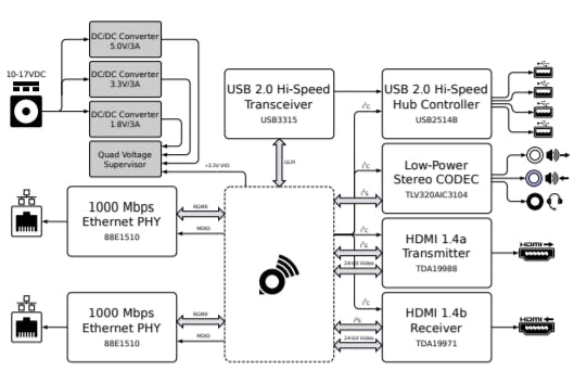
piSmasher Context Diagram (source https://krtkl.com/uploads/piSmasher-supplement.pdf)
The low power CODEC is connected to the programmable logic pins on the Snickerdoodle. Communication between the Snickerdoodle and the CODEC uses a protocol called Inter Integrated Circuit Sound (I2S). This allows us to work with a headset, line in and line out.
If you are not familiar with I2S it is fairly simple protocol it consists of serial data in and out,. This serial data is synchronous to a serial clock, while the channel (left or right) is identified by the LRCLK. Typically the I2S serial data is transmitted in words of either 16 or 24 bits.

I2S Waveform (source TLV320AIC DataSheet)
Logic Design
To create this design we are going to use the following IP blocks within the Vivado project.
- Xilinx I2S Receiver - Set for 16 Bits of Data
- Xilinx I2S Transmitter - Set for 16 Bits of Data
- Zynq Processing System
- HLS IP Core - This will be created using Vivado HLS once we have the initial audio chain passing data.
However, when the I2S receiver and transmitter are added to the design you will notice that both are masters. The CODEC does not have separate transmit and receive I2S interfaces, this means there is only SCLK, LRCLK, Sin and Sout.
As both Xilinx IP both provide SCLK and LRCLK as masters we cannot interface them to the CODEC which only has one SCLK and one LRCLK.
To be able to interface with the CODEC we need first to convert the I2S transmitter to be a slave such that it uses the receivers SCLK and LRCLK.
This option is not available in the standard IP customization flow, instead we do this by selecting the I2S transmitter and enabling selecting Block Properties.
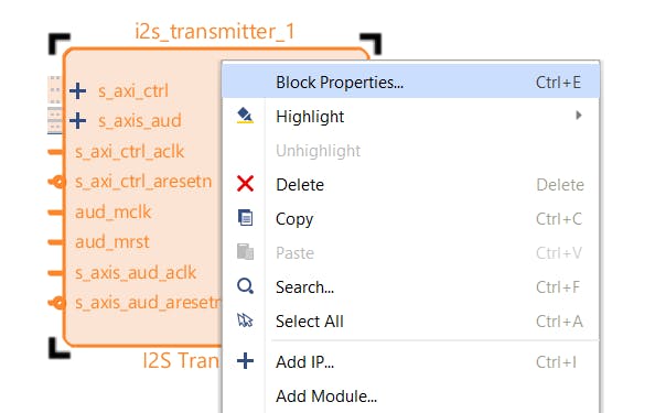
Selecting the I2S Transmitter Properties
Within these properties you should see the under config a option called C_IS_Master change the value of this from 1 to 0.
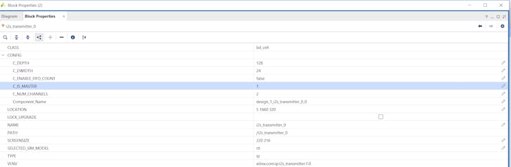
Initial parameters of the I2S Transmitter
Modified Parameters as below

Changing the parameters of the I2S Transmitter
Once this is completed you will see the I2S Transmitters SCLK and LRCLK are now inputs to the transmitter and not outputs.
We can now complete the design in Vivado
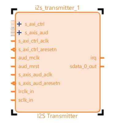
Updated I2S Transmitter Configured as a Slave
We control the CODEC over a I2C link, this configures the CODEC settings and its internal routing.
The I2C pins on the CODEC are connected to the PS MIO on the Zynq, therefore we also need to configure the Zynq Processing system to enable I2C_1 connected to MIO pins 24 and 25.

Enabling the I2C in the Processor System
We are then in position to implement the first Audio pass through design without the HLS Block.
This enables us to demonstrate we can configure the CODEC correctly and that we can pass I2S signals through the programmable logic. For this design we connect the I2S receiver and transmitter back to back. This is simple to do as both blocks use AXI Streaming interfaces internally.
Along with the I2S signals we also need to provide a master reference clock, to the CODEC. This needs to be able to be dividable to the sampling rate of the audio in this case 48KHz. As such I configured Zynq Fabric Clock 1 to generate a 12 MHz clock, this is provided as a reference master clock to both the I2S Transmitter and Receiver along with the CODEC.
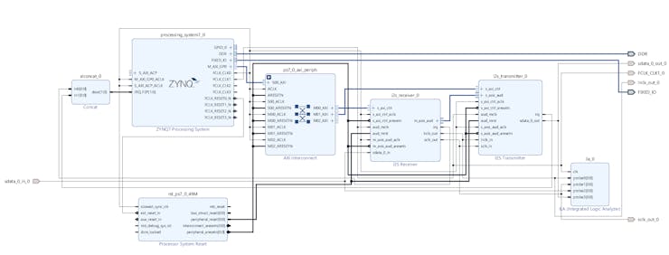
Initial Back to Back design
When we implement the design we need to be careful to ensure we do not get confused between the Data In and Data Out. They are named with respect to the CODEC so the Zynq Data Out is connected to the CODEC Data In and Zynq Data In is connected to CODEC Data Out.
The XDC file can be seen below.
set_property PACKAGE_PIN V20 [get_ports sdata_0_out_0]
set_property PACKAGE_PIN P20 [get_ports sclk_out_0]
set_property PACKAGE_PIN G14 [get_ports lrclk_out_0]
set_property PACKAGE_PIN N20 [get_ports FCLK_CLK1_0]
set_property PACKAGE_PIN W20 [get_ports sdata_0_in_0]
set_property IOSTANDARD LVCMOS18 [get_ports sdata_0_out_0]
set_property IOSTANDARD LVCMOS18 [get_ports lrclk_out_0]
set_property IOSTANDARD LVCMOS18 [get_ports sclk_out_0]
set_property IOSTANDARD LVCMOS18 [get_ports sdata_0_in_0]
set_property IOSTANDARD LVCMOS18 [get_ports FCLK_CLK1_0]
Software Development
We can then build the design in Vivado and export it to Xilinx SDK and develop the software application.
This software application needs to do the following
- Configure the PS GPIO - MIO 18 is connected to the CODEC reset
- Configure the PS I2C
- Configure the I2S RX
- Configure the I2S TX
- Configure the CODEC over I2S
To ensure the CODEC responds properly the first thing we need to do is reset the CODEC. We can then write in to the CODEC its configurations for the Line 1 Input and the Left and Right Output.
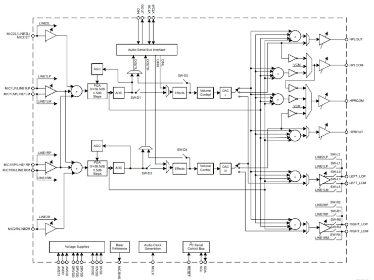
Block Diagram
As you can see from the block diagram of the CODEC we can route signals either entirely through the CODEC or we can pass signals in and out via the Audio Serial Bus which is what we want.
All this configuration uses the I2C channel so the first thing is to prove that the I2C channel is working correctly and that we can read and write over the I2C link.
To do this I created two simple I2C read and write functions
void i2c_write(u8 reg_addr, u8 reg_value){
	int Status;
	SendBuffer[0]= reg_addr;
	SendBuffer[1]= reg_value;
	Status = XIicPs_MasterSendPolled(&Iic, SendBuffer,2, IIC_SLAVE_ADDR);
	if (Status != XST_SUCCESS) {
		return XST_FAILURE;
	}
	while (XIicPs_BusIsBusy(&Iic)) {
		/* NOP */
	}
}  void i2c_read(u8 reg_addr){
	int Status;
	SendBuffer[0]= reg_addr;
	XIicPs_SetOptions(&Iic,XIICPS_REP_START_OPTION);
	Status = XIicPs_MasterSendPolled(&Iic, SendBuffer,1, IIC_SLAVE_ADDR);
	if (Status != XST_SUCCESS) {
		return XST_FAILURE;
	}
	Status = XIicPs_MasterRecvPolled(&Iic, RecvBuffer,1, IIC_SLAVE_ADDR);
		if (Status != XST_SUCCESS) {
			return XST_FAILURE;
		}
	XIicPs_ClearOptions(&Iic, XIICPS_REP_START_OPTION);
	while (XIicPs_BusIsBusy(&Iic)) {
		/* NOP */
	}
}
Along with checking in the I2C performance in the software application I used a scope to check the physical I2C lines also.
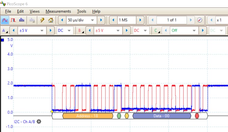
I2C Transaction
The software then needs to configure the CODEC to for the correct operation this includes
- Setting the PLL for 48KHz operation from a 12 MHz Master clock
- Setting the CODEC to be a slave
- Configuring the PGA, ADC DAC and R/LOPM channels
We then also need to configure the I2S RX and TX cores, for use in the application.This is straight forward as we can use the APIs provided by the BSP besides enabling the cores we need to tell both the sampling clock frequency.
As in the CODEC the sample clock is 48KHz this is generated from the Master Clock which is 12 MHz. Thus the Master Clock is 250 times the sampling clock rate.
We then also set the Audio Channels and enable the RX and TX cores.
XI2s_Rx_SetSclkOutDiv(&I2sRxInstance, I2S_RX_MCLK,I2S_RX_FS);
XI2s_Rx_SetChMux(&I2sRxInstance, 0x0, XI2S_RX_CHMUX_XI2S_01);
XI2s_Rx_Enable(&I2sRxInstance, TRUE);
XI2s_Tx_SetChMux(&I2sTxInstance, 0, XI2S_TX_CHMUX_AXIS_01);
XI2s_Tx_Enable(&I2sTxInstance, TRUE);
Probing the MCLK with an oscilloscope shows the desired frequency is provided to the CODEC.
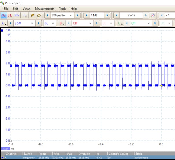
MCLK provided from the PL to the CODEC
When the developed software application was run on the Snickerdoodle with an audio source connected. I could observe the I2S data being received from and transmitted to the CODEC.
Plugging in earphones I could also hear the same music track being played by the audio source. To demonstrate the audio feed was routed through the Zynq disabling the I2C receiver while debugging would stop the audio output while re enabling it would resume the audio output.

I2S Interface between the Zynq and CODEC
With a transparent path created the next step is to create a High Level Synthesis bock which can be inserted in the AXI Stream and used for modification of the audio stream. This modification could be filtering, reverb, echo, delaying one channel etc.
Creating HLS IP Core
Within Vivado HLS we need to create a new project targeting the same device which is fitted to the Snickerdoodle.
For this application the clock frequency of the AXI Stream between the I2S RX and TX is 50MHz.

Once the project is created we need to create two files one CPP and one HPP file.
Within the HPP file we will declare a type definition which will allow us to work with the AXI Streams on the interface of the HLS IP Core.
To support the AXI Stream used by the I2S Tx and Rx cores we need to use the ap_axiu type defined by ap_axi_sdata.h
app_axi_sdata.h - AXIS interface definition we will be using
template<int D,int U,int TI,int TD> struct ap_axiu{ ap_uint<D> data; ap_uint<(D+7)/8> keep; ap_uint<(D+7)/8> strb; ap_uint<U> user; ap_uint<1> last; ap_uint<TI> id; ap_uint<TD> dest; };
This enables us to declare a AXI Stream elements, and create a stream of these elements
#include <ap_fixed.h>
#include <ap_axi_sdata.h>
#include "hls_stream.h"
typedef ap_axiu< 32, 1, 1, 1> AXITYPE;
typedef hls::stream<AXITYPE> AXI_STREAM;
void audio_top(AXI_STREAM& AudioA, AXI_STREAM& AudioB);
Once this is completed within the CPP file we can create a simple function which uses the AXI Stream for input and output.
For this block it is going to be simple as passing the input to the output, we do this using a stream read and write as can be seen below. The intermediate variable dataInA is a AXI Element.
As we want this transfer to run continually a while loop is used.
#include "audio.hpp"
void audio_top(AXI_STREAM& AudioA, AXI_STREAM& AudioB){
#pragma HLS INTERFACE axis port=AudioA
#pragma HLS INTERFACE axis port=AudioB
AXITYPE dataInA;
while(1){
	 dataInA = AudioA.read();
	 AudioB.write(dataInA);
	}
}
With the simple code written the next stage it to perform C Synthesis. If we had written a complex filter we may want to create a C Test bench first to demonstrate the correct behavior.

Results of C Synthesis
The final step in Vivado HLS is to package the IP core and export it for use in Vivado.
Updating the Vivado Design
Within Vivado open the IP Catalog select the user repository and right click, to bring up a menu. From this menu select the Add IP to Repository and select the zip file which was created by Vivado HLS
This compressed file will be available under
<hls project name>\solution1\impl\ip
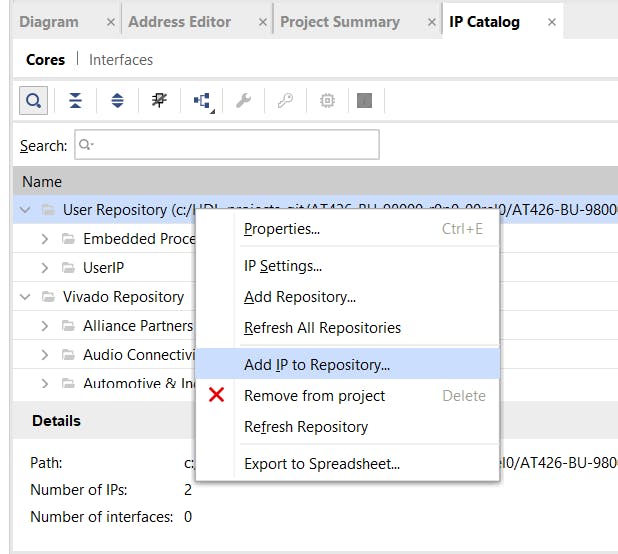
Adding the HLS IP to Vivado
Once this has been imported you will see the Audio_HLS block available within the user repository

Audio HLS Block available
We can now add IP core in to the Vivado design between the I2S Rx and I2S Tx on the AXI Stream.

Updated Vivado Design with the HLS Block included
To ensure the HLS block runs repeatedly I connected the ap_start input on the HLS block.
When I put this all together the the video below shows the system working as it should.