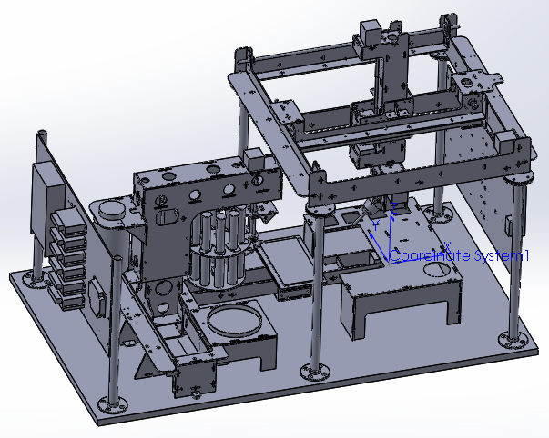
-
bitmap image to paint stroke g-code - part 1
08/22/2019 at 21:26 • 0 commentsFour days, seven coffee shops, and 750 lines of code later and I am getting very close to finalizing the Python project that can generate the If Then Paint prototype machine g-code from bitmap images. It's been a little over two years since I first starting developing the code. I figure it's time to finally describe the process from image to g-code and detour to some of my favorite challenges that I encountered along the way.
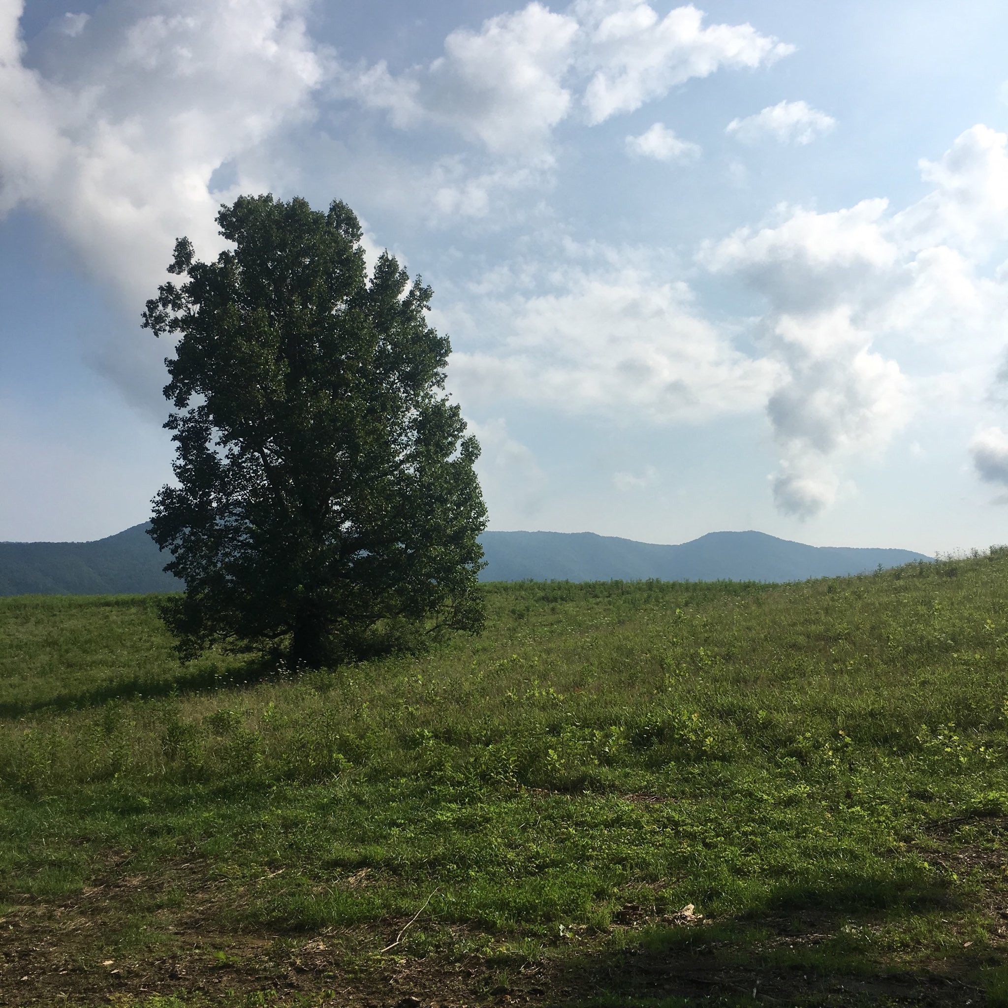
It starts with an bitmap image. In this case, it is a picture of a tree in a meadow that my wife took on our last vacation.
![]()
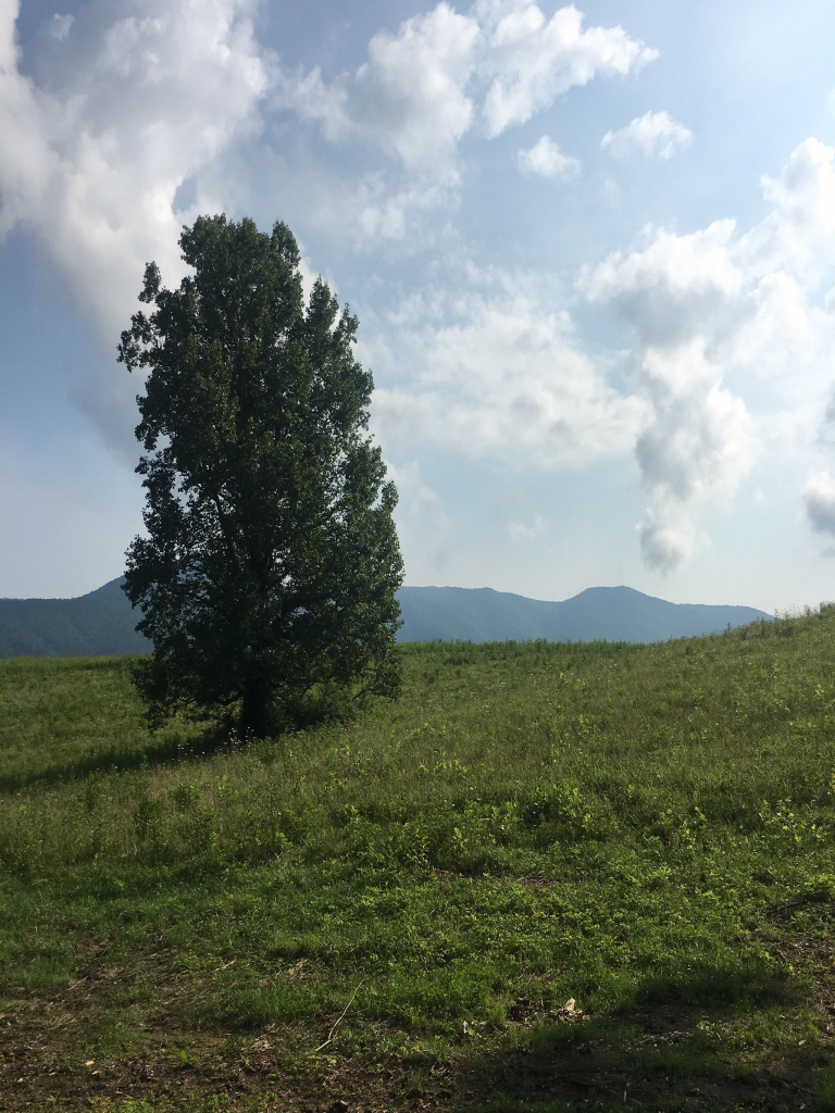
The bitmap image then gets sized to match the aspect ratio of the physical canvas and resolution of the digital canvas (see sized image below). If we didn't want to lose the proportions of the original image, we can just open the original image in an image manipulation program, cut out the desired section of the image with the same aspect ratio as the physical canvas, save the section as a new image, treat the new section image as a new original image, and perform the sizing process. I have chosen not to keep the original image proportions to make it easier to visualize what the resizing process is doing. The image is sized to the resolution of the digital canvas because a spatial reference between pixels and millimeters is needed. The If Then Paint prototype uses a 768x1024 digital canvas resolution for a 120x160mm physical canvas (i.e. 6.4 pixels per mm).
![]()
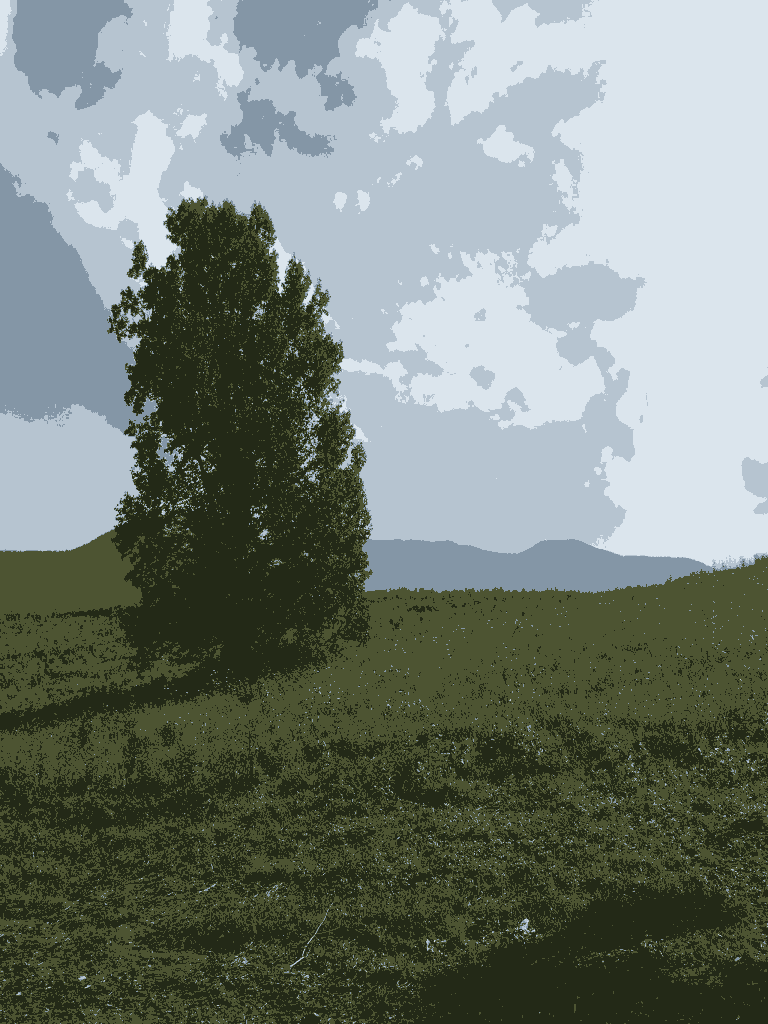
The next task is to simplify the image to only a few colors using color quantization. The image below is reduced to just five colors. The primary reason for reducing the number of colors is to reduce the number of paint colors that need to be mixed to create the image. The original bitmap image might have hundreds of colors. Mixing hundreds of colors will take a long time and the final painting might actually look better with fewer colors.
![]()
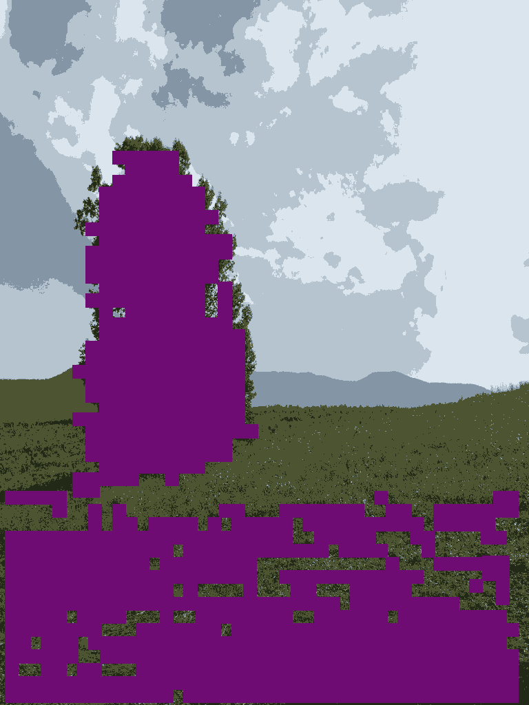
After color quantization, we can start to apply the secret sauce of this image to g-code recipe - the algorithm that generates paint stroke options from the bitmap image. With a simple horizontal and vertical scan of the dark green color, we get the following possible paint strokes (shown in purple for contrast but also for fun). The next project log will dive deeper into the details of the algorithm.
![]()
-
machine control dimensions
08/16/2019 at 04:01 • 0 commentsIn contrast to 3D printers and cnc mills that only have one or two objects to interact with within the workspace (e.g. bed and stock material), the cnc painting machine interacts with multiple objects like the canvas, towel, water, and paint palette. The tables that follow detail the object dimensional information needed to develop the cnc painting machine control instructions (gcode) for the If Then Paint proof of concept prototype. Most of these dimensions are fixed, but some may need to adjusted as the gcode is developed and tested (z_water_dip for example).
You will see paint palette object dimensions for both the six axis brush machine and paint management machine because both interact with the paint palette but in their own coordinate systems.
Six axis brush machine control dimensions (tool docks, brush cleaning water, brush wiping towel, canvas, and paint palette objects):
Dimension Value Units x_tool_dock_1 -88.5 mm x_tool_dock_2 -23.5 mm x_tool_dock_3 41.5 mm x_tool_dock_4 106.5 mm y_tool_dock 229.75 mm z_tool_dock 3.5 mm z_tool_dock_clearance 15 mm x_water 109 mm y_water -61.75 mm z_water_dip -62 mm z_water_clearance 15 mm water_dip_radius 15 mm x_towel_start 45 mm x_towel_end -100 mm y_towel 75 mm z_towel 2 mm z_towel_clearance 15 mm x_home_to_x_canvas_left -253.35 mm y_home_to_y_canvas_bottom -323.9521 mm z_canvas 2.5 mm z_canvas_clearance 15 mm x_palette_left -129.0616 mm y_palette_top 189.75 mm z_palette -7.075 mm z_palette_clearance 15 mm Paint management system machine control dimensions (paint palette, dispenser, syringe water, and paint objects):
Dimension Value Units x_palette_left 5 mm x_palette_right -95 mm y_palette_top -73 mm z_palette -173 mm z_palette_clearance 15 mm x_dispenser -121.6146 mm x_water -61.6146 mm y_water -372.9771 mm z_water 2 mm z_water_clearance 15 mm a_paint_1 0 deg a_paint_2 36 deg a_paint_3 72 deg a_paint_4 108 deg a_paint_5 144 deg a_paint_6 180 deg a_paint_7 216 deg a_paint_8 252 deg a_paint_9 288 deg a_paint_10 324 deg b_push_start 13 mm -
origin and axis orientations
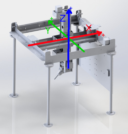
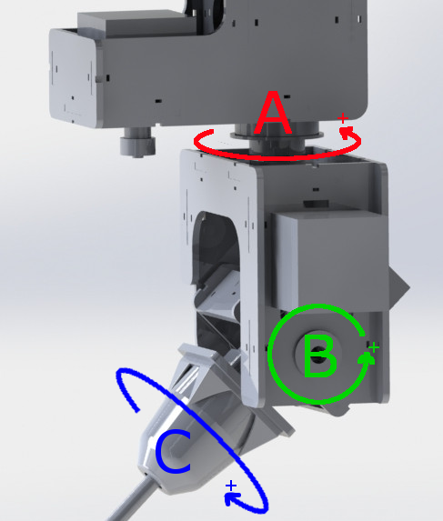
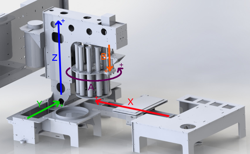
08/14/2019 at 17:00 • 0 commentsI developed the following graphics to help clarify the location of the origin and orientation of system motor axes. My hope is that these graphics will make it much easier to discuss motion control strategies for the If Then Paint cnc painting machine moving forward.
The origin of the six axis cnc brush control machine is located at the bottom left corner of the canvas. The paint management system does not have an absolute origin. Instead, it has a home position at the -x, -y, and -z limits of the paint management system axes.
The arrows point in the positive direction of the depicted axis. All axes have the capability to move in both directions.
![]()
![]()
The x-axis positive direction is into the paint carousel. When developing the machine movements, it's generally easier to think about machine movements relative to the "tool" (i.e. paint dispenser in this case). Since the bed (i.e. palette) is moving and the tool is stationary, a bed positive movement towards the tool can be thought of instead as a tool positive movement across the bed.
![]()
-
bitmap image to paint stroke examples
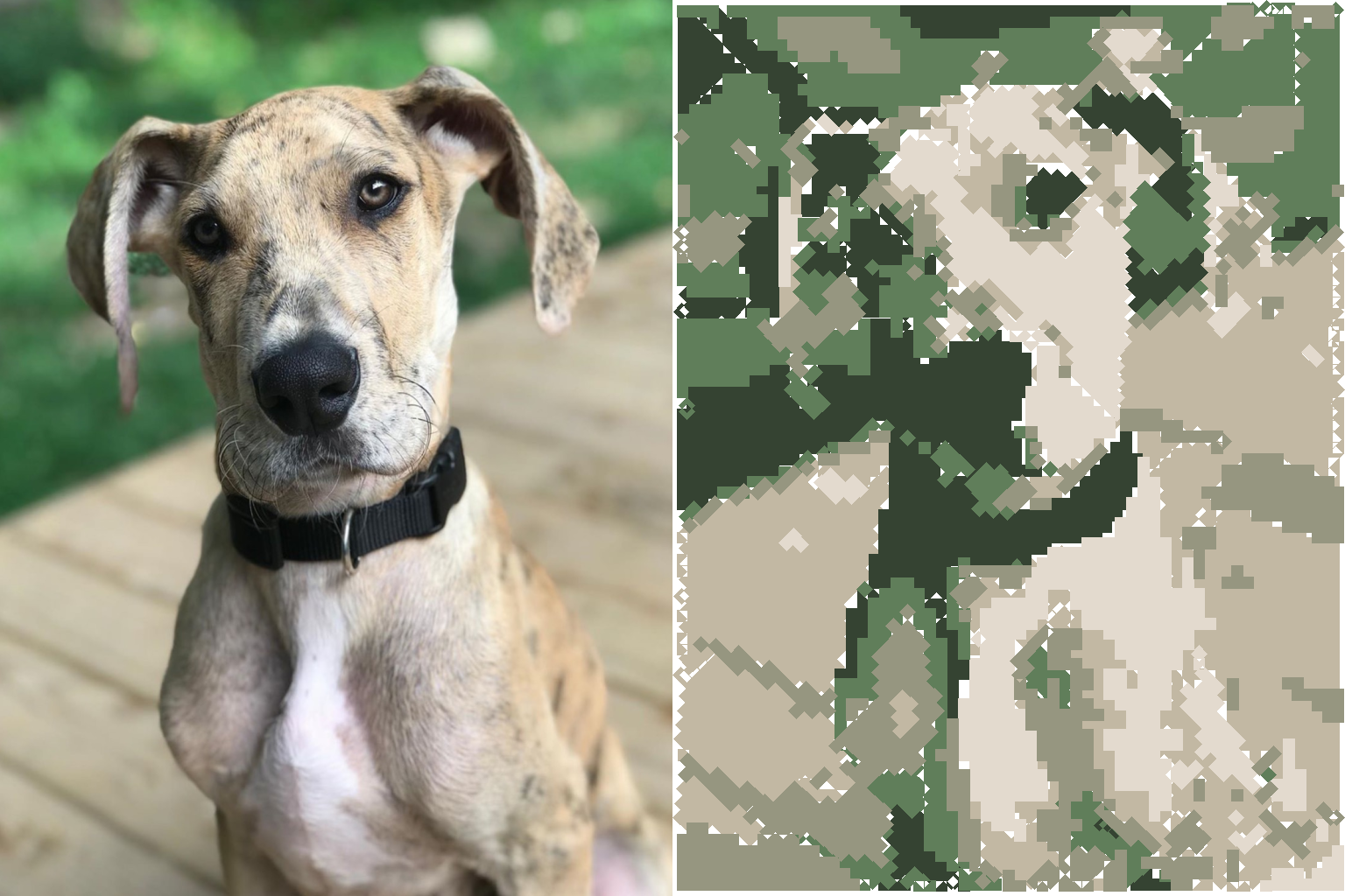
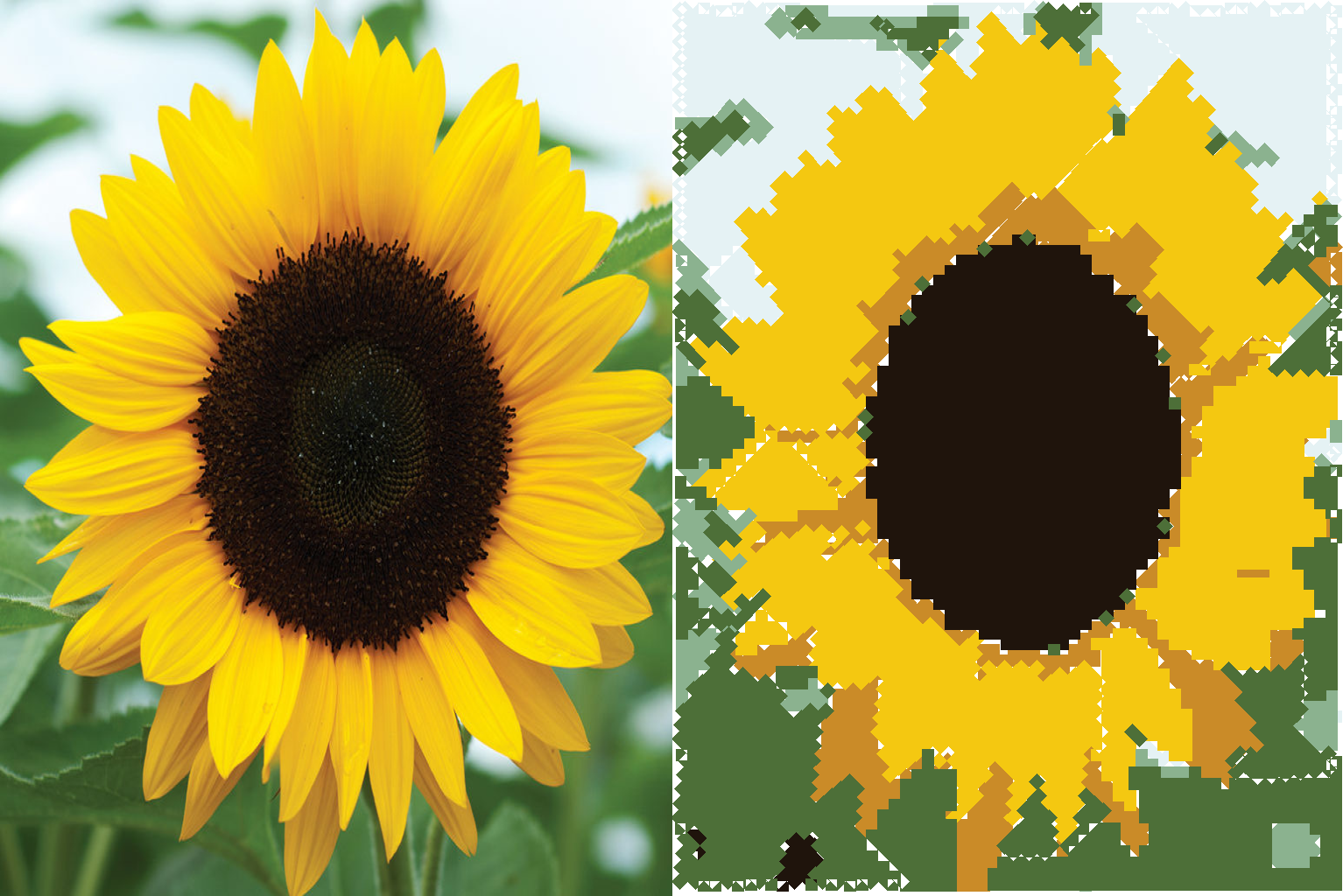
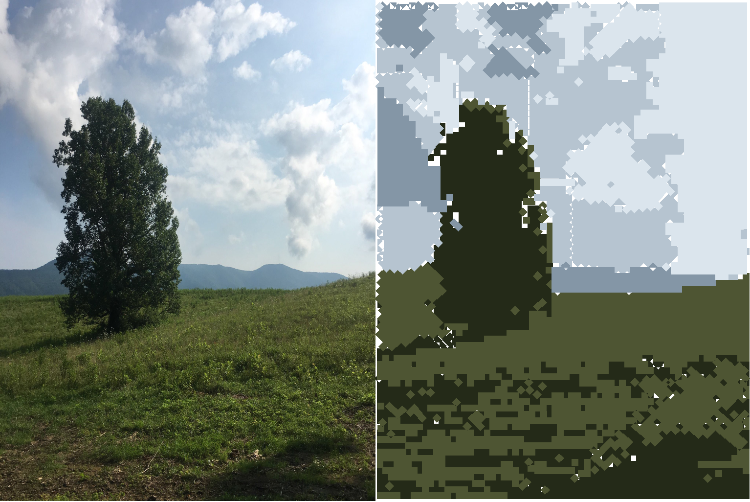
08/07/2019 at 03:35 • 0 commentsOne of my goals this week was to explore what bitmap image to paint stroke conversions are possible with very simple conversion parameters. In the three image conversion examples below, the original reference image is on the left and paint stroke preview image is on the right. None of the images are a result of being physically painted by a cnc painting machine. The preview images are just approximations of what a final painted image might look like. The longest line algorithm (described in a previous project post) was used to generate paint strokes from the reference image. The generated paint strokes were plotted in their respective colors to construct the preview images. A single round brush size and no more than six paint colors were used to construct each preview image. Even with these simple parameters, the paintings are still fun to look at and given past experience, they will probably look much smoother as actual paintings. The rough and jagged borders between colors shown in the preview images are less striking once physically painted. These conversions get me excited about what might be possible with more complex parameters.
Another thing I really enjoy about these conversions is that even though I know what the reference image looks like and the painting parameters that the algorithm is using, the result can still be surprising. For example, it's always interesting to me how the algorithm removes detail from the original image, but in some way the message and feeling of the image is not lost. Like the fine details are not what really mattered.
This also motivates me to fully develop the paint management system. Without the paint mixing component of the paint management system, I currently have to manually mix paints until the correct color is achieved. Once fully developed, I won't have to mix paints anymore and painting with more than six colors should no longer be much of a challenge.
![]()
![]()
![]()
-
fabrication files posted
08/01/2019 at 02:03 • 0 commentsAll fabrication files needed to build the cnc painting machine have been released to the GitHub repository: https://github.com/johnopsahl/IfThenPaint_FabricationFiles
The fabrication files are listed separately for the two cnc subsystems - the six axis cnc and paint management system. Six laser cut 12x24in sheets of 0.175in baltic birch plywood and two 3d printed parts are required for the six axis cnc machine. Ten laser cut 12x24in sheets of 0.175in baltic birch plywood and one 3d printed part are required for the paint management machine. The bills of material include quantities and descriptions of all the purchased components.
A .step solid model file of the entire machine is included for dimensional reference as well.
-
cnc painting user interface wireframe
07/30/2019 at 02:19 • 0 comments![]()
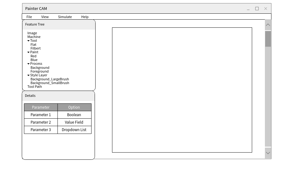
A few months back I tried to imagine what the cnc painting software user interface might look like. I arrived at the wireframe shown above. The "Feature Tree" box (left center) includes all high level components that need to be defined to both determine paint strokes from the bitmap image and create the cnc machine gcode painting instructions from the paint strokes. The user works from top to bottom in the feature tree. When the user clicks on and highlights an item in the feature tree, user input parameters unique to the tree item type are listed in the "Details" box (left bottom). In addition, feature tree item actions are accessed by right clicking on the feature tree item. The "Canvas" window (center, depicted as a white square) is where images are displayed. This includes images like the original bitmap image that is being converted to paint strokes, strokes of a specific brush displayed over the original image, strokes generated during a specific iteration of the algorithm, all paint strokes required to create the image, etc. It would be possible to zoom in/zoom out and pan in the canvas window. The "File", "View", and "Help"menu bar headers would contain the standard application features. The "Simulate" menu bar header would run a simulation of the cnc painting operation by showing a moving brush in the canvas window (similar to the simulation feature of a cnc milling CAM software). The simulation feature is somewhat advanced to implement and actually does not add that much value. It's unlikely it will be released in the first version of the software.
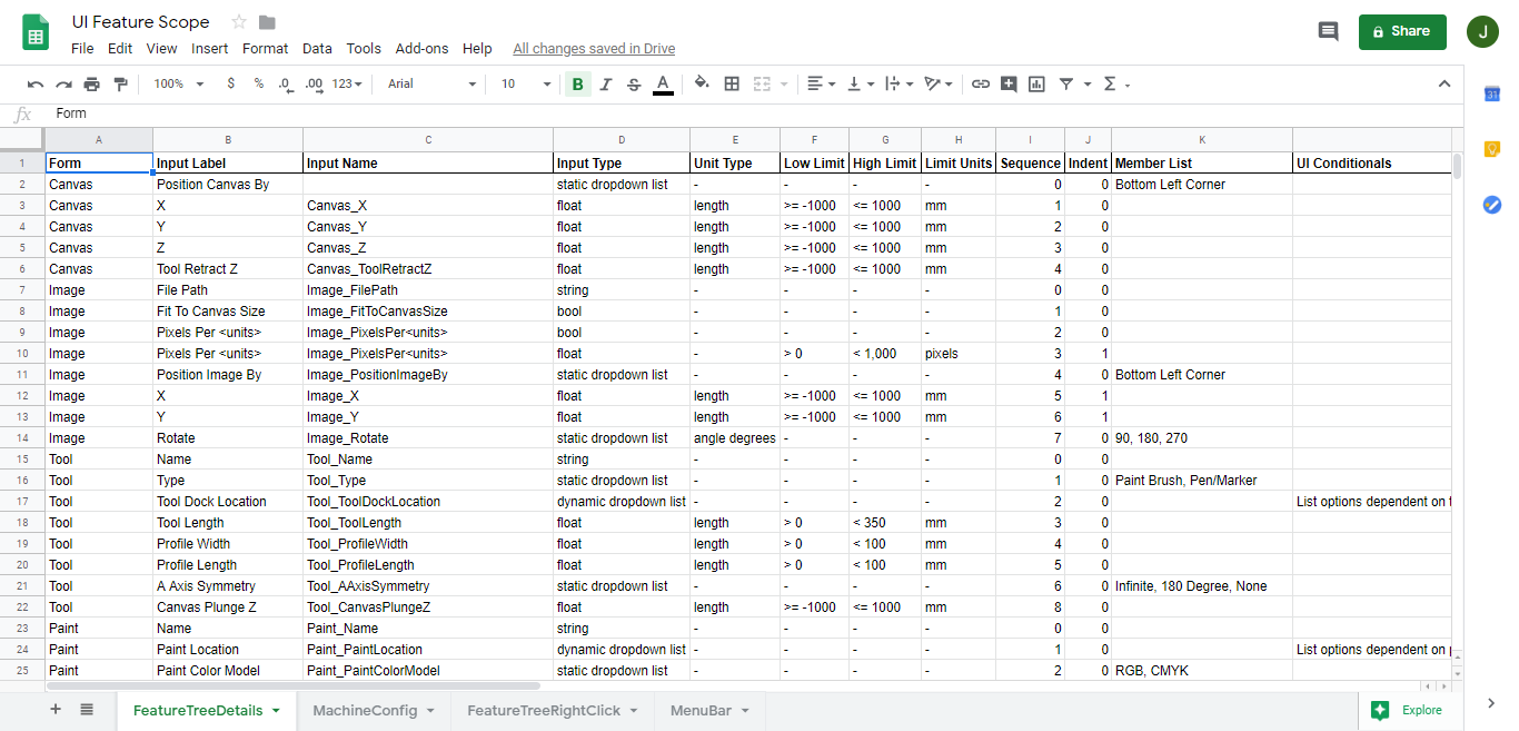
After completing the wireframe, I began scoping out the UI input fields and actions in a Google doc spreadsheet. The screenshot below is the list of input options that would appear in the details box when a feature tree item is highlighted.
-
cnc painting workflow
07/27/2019 at 04:19 • 0 commentsOnce fully developed, I envision cnc painting workflow to be very similar to the workflow used for 3D printing and cnc milling.
- Create a template file with using your preferred software. A bitmap image in the case of cnc painting using an image processing software like GIMP, Adobe Photoshop, Corel Paintshop, etc. A 3D model file in the case of 3D printing and cnc milling using solid modelling software llike Onshape, Autodesk Fusion 360, Solidworks, etc.
- Import the template file into the computer aided manufacturing software. The If Then Paint software for cnc painting. Splicing software like Cura or Simplify3D for 3D printing. Software with tool path creation capabilities like Autodesk Fusion 360 or Solidworks for cnc milling.
- Select which machine you are using. The software either loads the predefined machine parameters from a database or asks you to define the parameters for the machine.
- Make adjustments to the parameters that effect the tool path operations.
- Run a simulation that shows the result of the tool path operations. Observe how adjustments in step 4 affect the final product.
- Continue step 4 and 5 until you have a achieved a desirable result.
- Export the tool paths from the software as gcode.
- Upload the gcode to the cnc machine.
- Prep the cnc machine with any raw material needed.
- Run the gcode program on the cnc machine.
-
automated paint mixing
07/26/2019 at 17:57 • 0 commentsThe automated paint mixing component of this project is essentially a small scale recreation of going into the paint store with a color sample and leaving with a bucket of paint of that color.
The main challenge is determining which paints to mix to create the correct color. Paint companies have their own methods for predicting additive color mixing which most likely requires data from expensive photospectrometer equipment. Fortunately, cnc painting probably doesn't require the color matching accuracy that paint companies achieve.
I propose using a camera and cnc machine to develop the paint mixing color data needed for cnc painting. The cnc machine would dispense and mix paint color samples in various proportions (e.g. 20% white/80% red, 30% white/70% red, etc.). After those paint samples dry (because some paints change color once dry), the camera would take a picture of the sample in controlled light conditions. Using an image processing tool, an rgb value would be extracted from the picture of each sample. Then it is only a matter of finding the rgb values of the paint sample that are closest to the rgb values of the desired color, approximate the desired color as the paint sample color, and mix up the paint per the known color proportions of the paint sample to achieve an approximate paint color match. The accuracy of this method can be increased by increasing the number of stock paint colors and using finer increments of mixing proportions.
The method I am proposing is not a small task, but it should only have to be done once per grade/brand of paints. Whomever designs the paint mixing software would need to create the machine, dispense and mix as many paint samples as needed, and insert the paint mixing color data in the software as a database. The average maker and artist would make use of the database through the software and never need to perform this task.
-
automated paint management
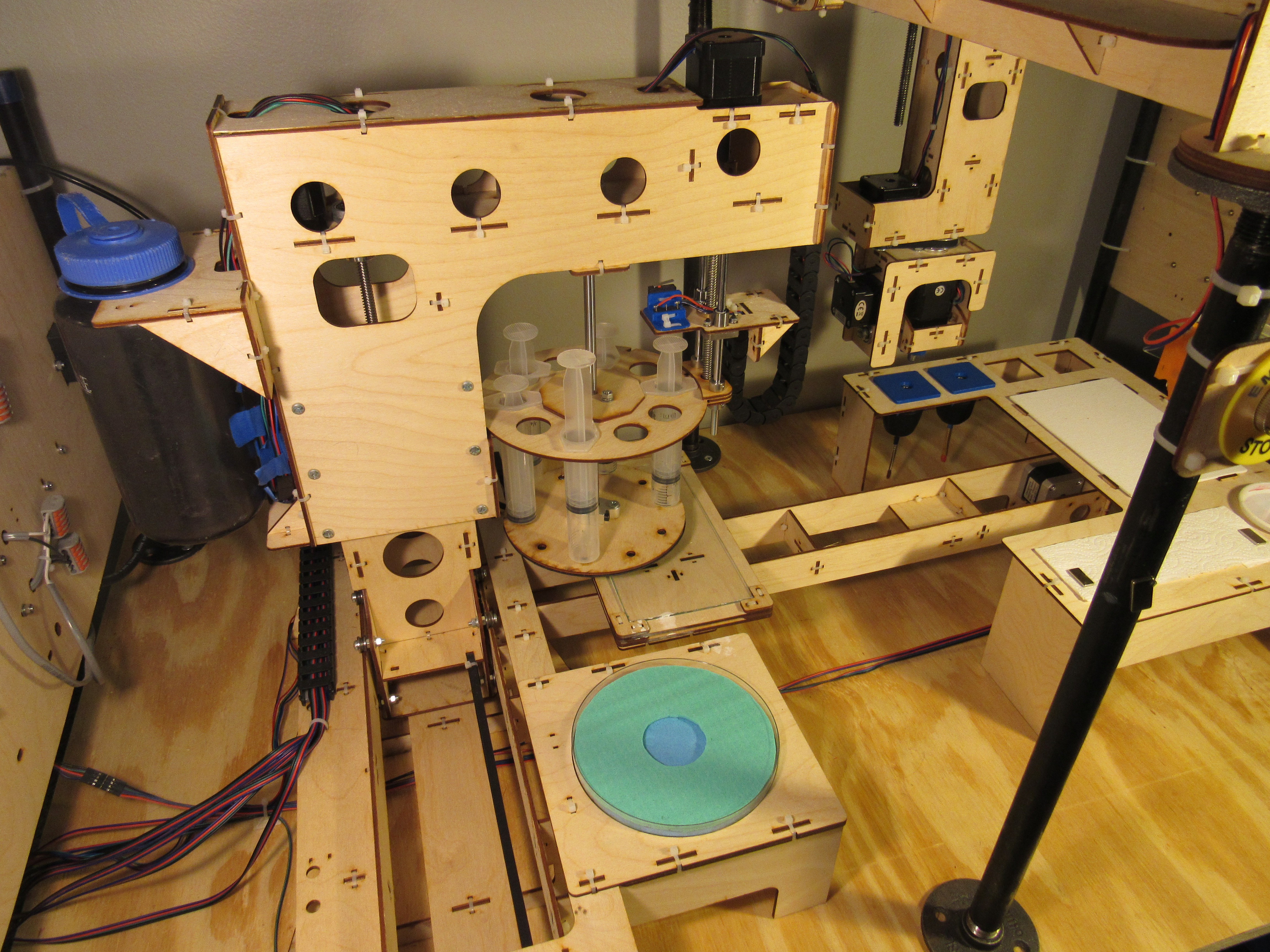
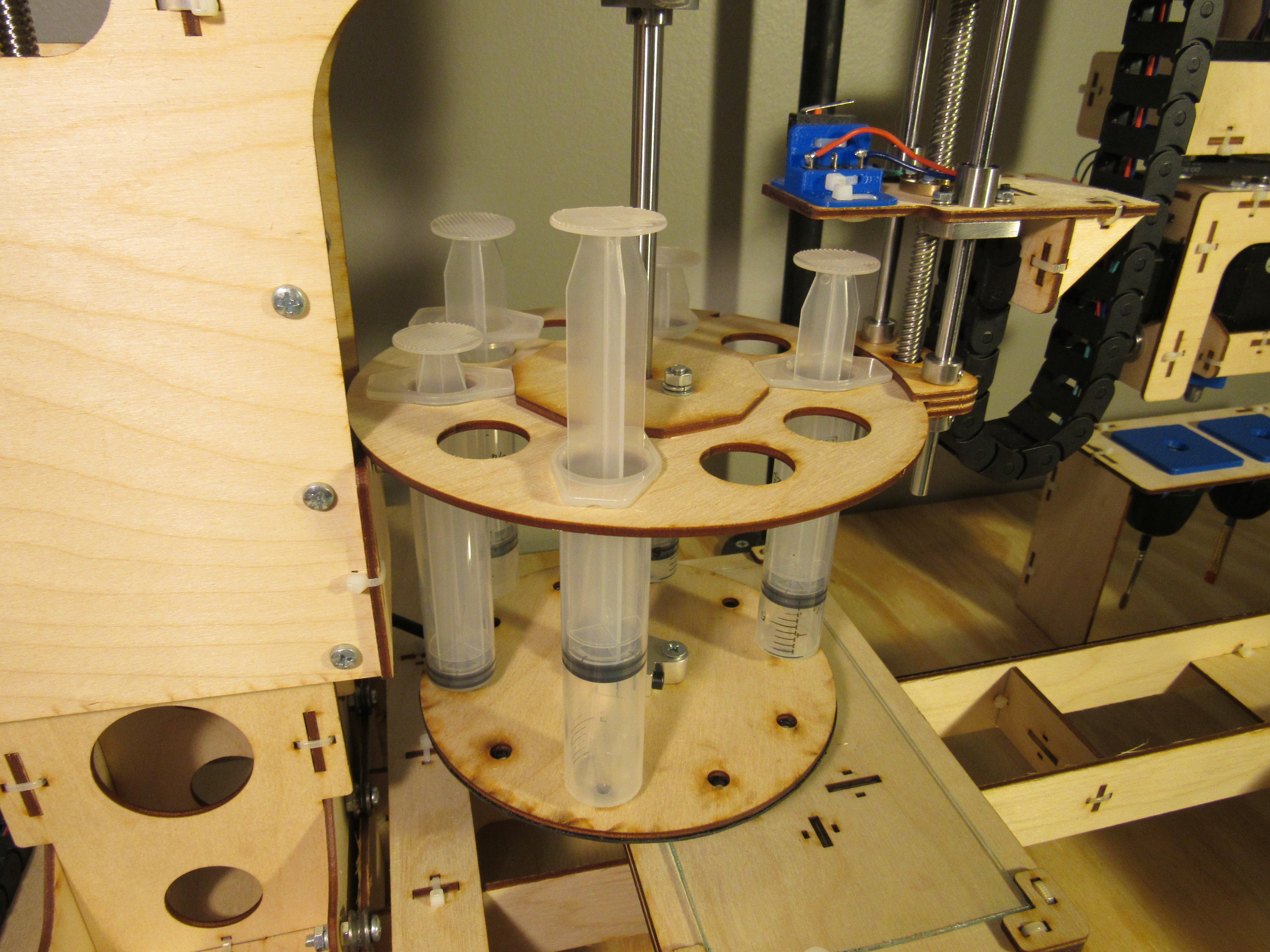
07/24/2019 at 03:47 • 0 comments"Paint management" refers to the processes involved in dispensing and storing paints during the cnc painting operation. The paint management system developed for the proof of concept prototype is comprised of a three axis positioning system, a syringe carousel and push plate, a paint palette, and a water dish. The three axis positioning system is used to dispensed paint at any location on the palette. The syringe carousel allows up to ten syringes of paint; one per paint color. The syringe carousel rotates to position syringes under the push plate. The push plate presses on the syringe plunger to dispense paint onto the palette. After use, the syringes are returned to the water dish so the paint doesn't dry and clog the tips of the syringes. The palette is made of glass so it can be cleaned easily using a metal scraper.
In theory, the paint management system will determine how much paint to dispense and where on the palette to put the paint by following this process. After the user has converted a bitmap image to paint strokes, another programming script determines the total paint stroke distance traveled on the canvas for each color of paint and each paint brush. Each paint brush has a predefined (determined through testing) parameter on how far it can travel on the canvas before needing to be reloaded with paint as well as the length of paint bead required to reload the brush. From this information, the length and color of each paint bead that needs to be dispensed on the palette to complete the painting can be found. Another script will map out how to place the variable length beads of paint within the available palette size. This map will be converted to the gcode instructions that get sent to the paint management system microcontroller.
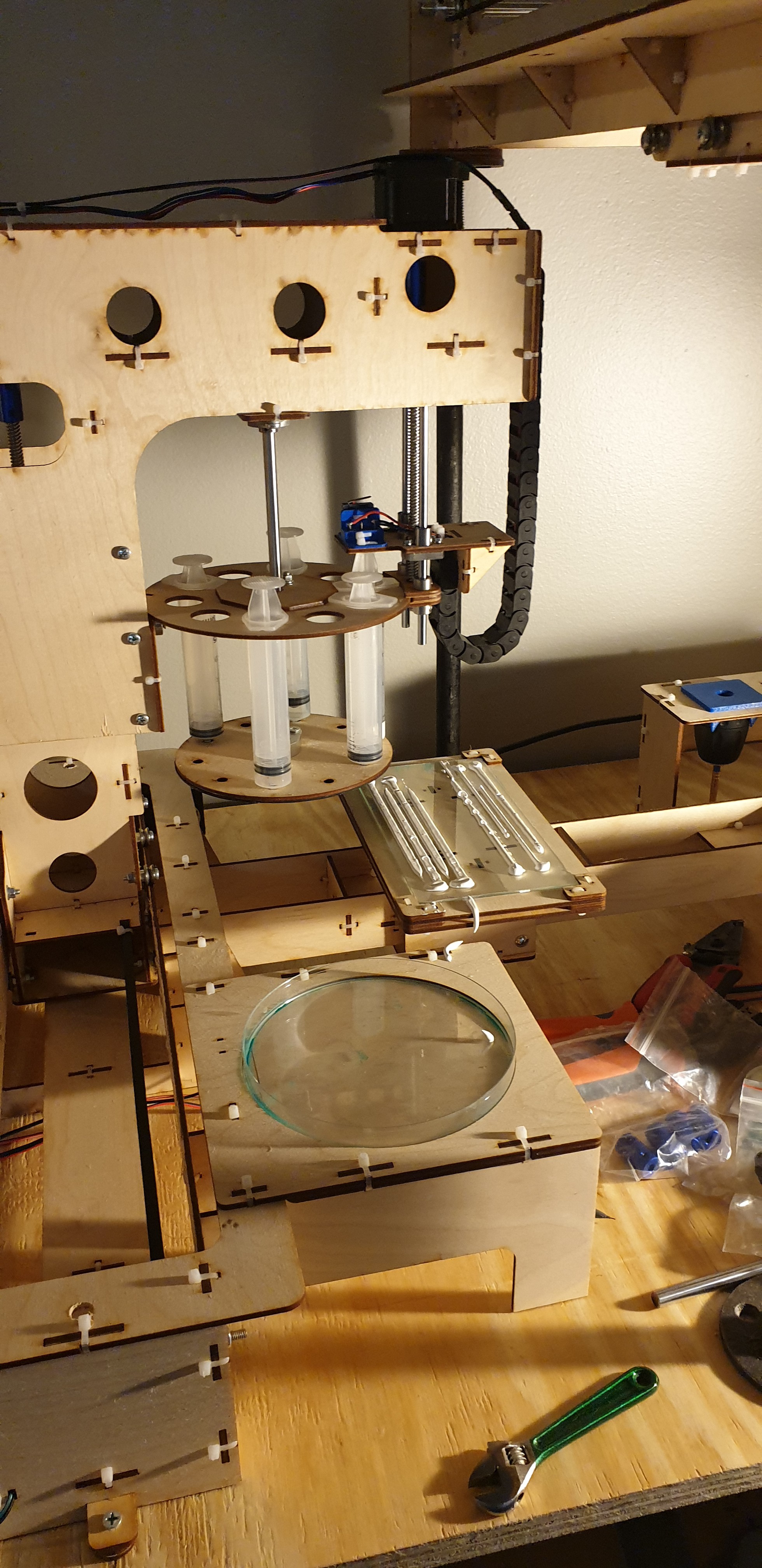
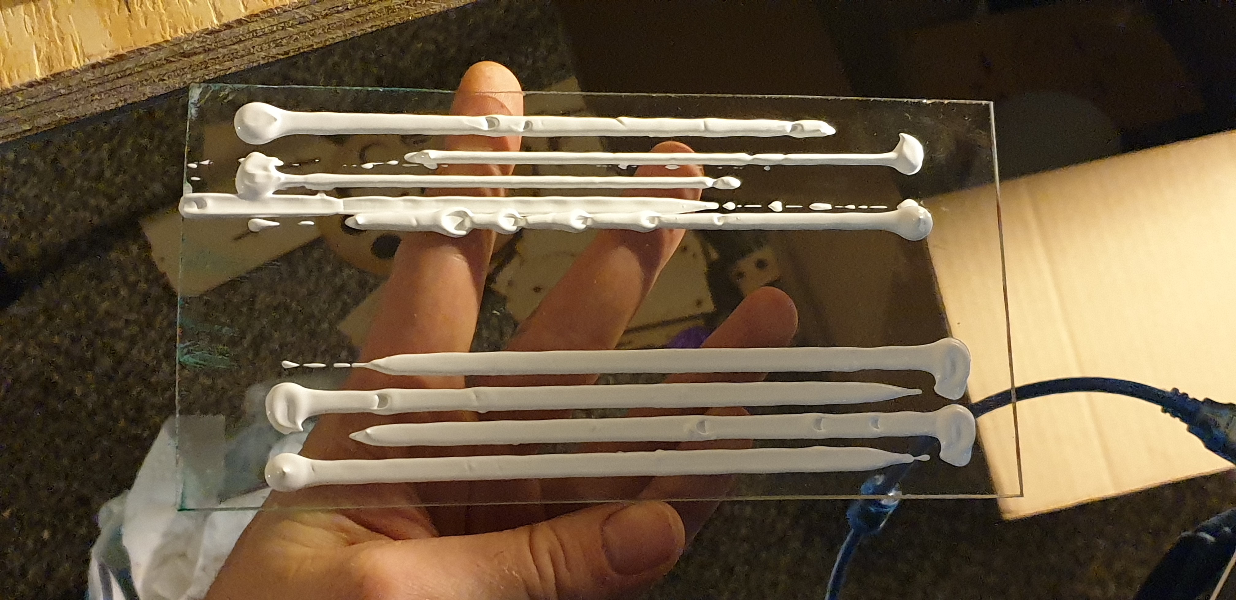
Turns out that acrylic paint is thixotropic (viscosity decreases with an increase in shear stress). When I commanded the machine to dispense paint and move all in one single movement there would be a delay before paint would start coming out of the nozzle. After the movement was completed the syringe continued to dispense paint. See the rows of paint at the top of the palette in the images below. I eventually figured out how to create uniform beads of paint by dispensing a little bit at the beginning and including a short delay so the paint could begin to flow before staring the movement. See the rows of paint at the bottom of the palette in the images below. It still needs some work but after a few months of designing and fabricating the paint management system I considered it a victory.
![]()
![]()
-
load brushes with paint without feedback
07/23/2019 at 04:36 • 0 commentsImagine you are trying to load a brush with paint with the intent of painting on a canvas. You have a paintbrush in one hand and a cup full of paint in the other. The catch is that you can't see inside the cup. You eventually get good at loading the brush with a known amount of paint by dipping it a distance into the cup. But after a while you've dipped it so many times now that you don't know of how much paint is left in the cup and what side of the cup the majority of the remaining paint is on. This is the challenge of loading brushes with paint without feedback (i.e. The challenge is knowing how much paint is left in the cup and how the paint is distributed within the cup).
One way to solve this problem is to use paint with low viscosity like tempera or liquid acrylic paints. Low viscosity ensures that the paint always settles to a uniform level in the cup. After that, it only takes some testing to determine how far the paint level in the cup drops each time the brush is dipped into it. Better yet, use a large container of paint so the paint level drops so little after each brush dip that the change in paint level can be neglected.
Another way would be to use high viscosity paints like oil and acrylic and continuously monitor paint distribution in each cup during the entire painting process. If a brush continues to dip in one location of a cup of high viscosity paint, eventually a well will form. The next time the brush dips into that location for more paint it will just be dipping in air. To combat this, paint needs to be periodically stirred in each cup until wells are gone and all paint locations in the cup are at the same level. Alternatively, the brush could be commanded to dip in the cup of paint at different locations each time.
I have used both methods with success but prefer to use high viscosity paints because of the rich color, less risk of dripping on the canvas, and three dimensional texture. At the moment, the cost of using high viscosity paints is being present during every second of the painting operation to make sure there is enough paint in each cup and to stir out any wells when they form. This is in conflict with the unsupervised operation proof of concept design requirement.
In search of a more complete method to load brushes with high viscosity paint, I stepped back and tried to understand the problem better. I knew that in order to repeatably apply a known amount of paint to a brush without feedback the geometry of the paint that the brush is dipping into has to be predictable. In the case of paint in a cup, the well formation and paint level are not easy to predict because they depend on factors like brush size and type as well as the viscosity specific to each brand of paint. Ultimately it's really just a paint side problem, the cnc machine can position the brush with accuracy and repeatability.
I kept digging deeper into the requirements until I realized that canvas painters had already solved half of this problem. The solution is... that simple flat surface called the painters palette. Not only is a good place to mix paints but a flat surface also makes paint easier to control. Think about wiping a brush on the side of a paint can after dipping the brush in the paint. The same concept is at play on a flat palette surface. You press the brush against a hard surface to better control how much paint is loaded into the brush.
The second part of the solution is my own contribution. To achieve predictable paint geometry, I propose dispensing paint into beads (like a bead of caulk) on the palette. To load brushes with paint, start on one side of the bead and each time that the brush goes back for more paint move a little closer to the other side of the bead. So that every time the brush goes back for more paint it dips into a previously undistributed section of the bead. The brush movement to load paint on the brush can be the same each time (though translated over after each dip) because the paint geometry is predictable.
Using beads of paint on a flat palette is my best guess at a method to load brushes with a known amount of paint without feedback. Developing an automated process for dispensing beads of paint onto a palette turned out to be as much of a challenge as the six axis cnc.
If ( ) Then {Paint}
a machine to create canvas paintings of your favorite digital images
 John Opsahl