Close
0%
0%

DIN Rail 10 channel LED PWM Dimmer

Use 10 channels of PWM dimming in an electric cabinet over Ethernet with the power of an ESP32

Similar projects worth following
Why use any bridged protocol to talk to LED dimmers over Ethernet? Why not go directly?
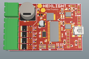
This project provides a 10 channel PWM LED Dimmer for installation in an electric cabinet (DIN Rail)

What are the possibilities to control some LED lights in your home?
Normally you would buy a small wireless enabled controller and install it where your light/lamp is. As the number of light sources rise this is only a half-viable option...
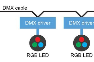
The other method is to use a "big" dimmer in your electric cabinet. These are typically controlled via a dedicated control-system. For example DMX, RS485, etc.

Last year, we've developed a versatile and cheap Ethernet DMX Bridge (german) to address the second option. These are used with DMX dimmers, partly in electric cabinets, partly for a DMX bus around the house.
Then I thought, why do I have to detour over DMX while I talk via Ethernet to the LED channels? Thus the idea for a standalone networked LED dimmer was born.

In the beginning we used WizNet's W5500 ethernet chip, which is well known in the Arduino universe, together with an ESP32. This network IC works absolutely fantastic together with Paul Stoffregen's marvelous Arduino Library. But as the project advances we came to the conclusion to use MicroChips's LAN8710 as this is far better supported in the used Espressif IDF for the ESP32. Thank you wESP32 and Olimex for the idea...

On the dimming side we've choosen the PCA9685 from NXP, which gives us 16 possible channels with 12-bit resolution and a configurable PWM frequency of up to 1526Hz. Because of that we now have 4096 brightness levels per channel.
The output is driven by 10 individual IRFR4105Z HEXFET's which can supply up to 21-30A.

As we have some space constraints in a 107mm wide (6TE) DIN rail case, only 10 channels of the possible 16 are available. We decided to have 8A per channel maximum and designed the spacing and pcb trace width and thickness accordingly.

We only use networked communication as Wi-Fi is often is not suitable in an electric cabinet. The ESP32 can do Wi-Fi anytime, but this was not what we aimed for in the first place.

The hardware and software will be open source. Currently we have 5 working prototypes and have to finish the software to get something we can show to the world.
Afterwards we are planing to sell these complete with CE marking and RoHS conformity in Germany.


So, this for the start. I will update as soon as there are any further steps taken.

Cheers!

  • Updating the Software and EMC testing

    Patrik Mayer07/30/2020 at 16:54 3 comments

    Software and Webinterface

    Well, despite the current situation we are making progress regarding the software development. m0fa is doing a great job by implementing the needed features using the Espressif IDF.

    In the first version the firmware only handled UDP communication on a given port, mimicking the procotoll of our DMX-Bridge. In the meantime the dimmer can speak UDP, HTTP, Websocket and MQTT which is all configurable in the webinterface.

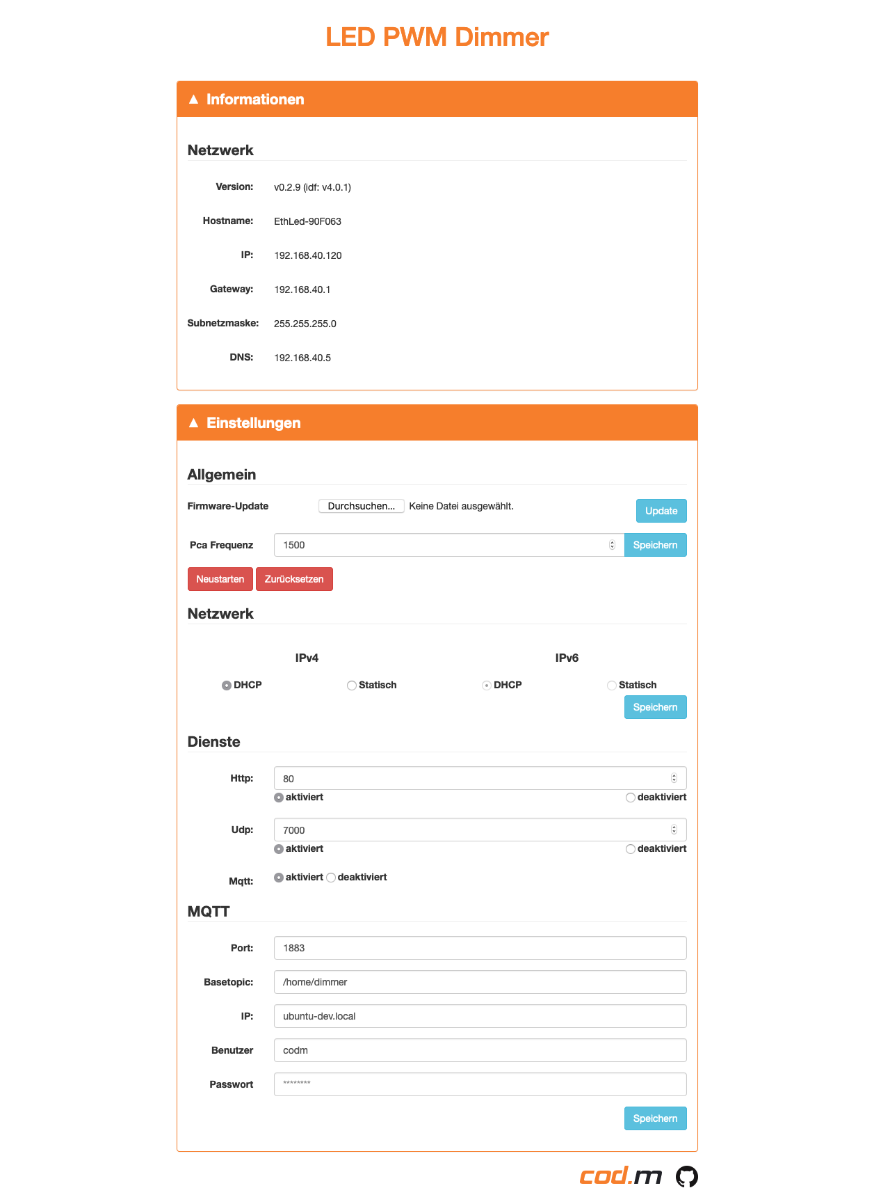
    The webinterface is work in progress, of course used to configure the device (Network, MQTT-Broker, Ports, etc.) and firmware upgrade but can also be used to dim the ten different channels directly. The screenshot shows a basic version without the sliders for the PWM channels.
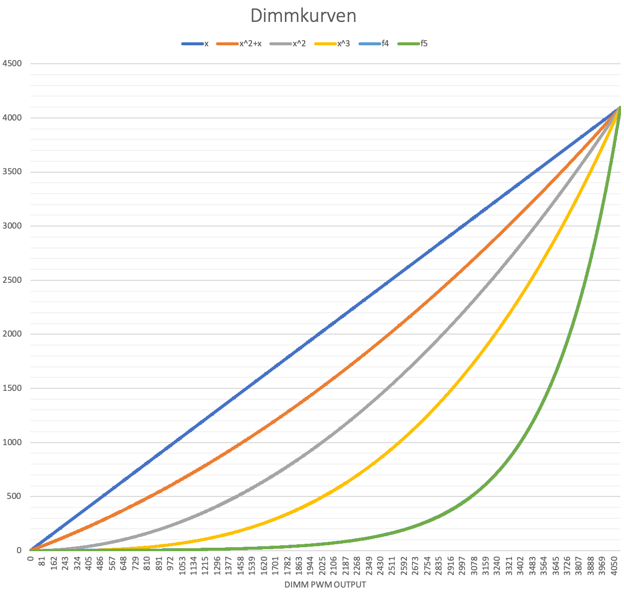
    Also there will be a possibility to configure the PWM properties, such as the overall PWM frequency as well as the used dimming curve per channel and transition time. These values can be overridden which each control command.

    We plan the following features for the first software release:

    • DHCP/Static IP (v4) adressing, unique MAC
    • Webinterface for settings and operation
    • UDP protocoll like the DMX-Bridge
    • MQTT with configured broker
    • Websocket connection
    • HTTP-Control-Interface with small limitations
    • Adjustable PWM frequency from 300-1500Hz (all channels)
    • Configurable dimming curve and speed for each channel

    EMC Testing

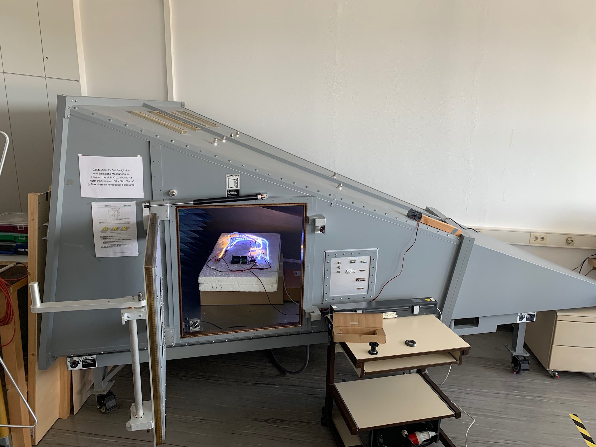
    As the final version of the DIN-Rail LED PWM Dimmer is approaching we had to make sure, that the device is compliant to european CE conformity guidelines - thus making sure that we comply with EMC/EMV.

    To do that we got in contact with the local University (THM) who run a decent EMC testing laboratory and give local companys access to it. We had our first run together with two professors, who guided us through the process of meassuring and taking counter meassures if something went of the scale.

    Indeed we designed the Dimmer accordingly and will only have to do minor changes. The next step will be optimizing the PCB and revise the load-FET's to completely comply with the EMC-CE guidelines. 

    As always keen on your input/feedback. I'll keep you updated.

    Cheers,
    Patrik

  • Real-World Tests and fixed i2c communication

    Patrik Mayer12/04/2019 at 16:15 2 comments

    Just wanted to give you guys a short update.

    We've finally found an homer-like flaw (doh) in the i2c communication to the PCA9685. Some idiot (me) forgot to tie the address lines of the PCA to ground properly. So in some raw situations the chip decided to change it's I2C address while communicating, thus resulting in kernel panic's on the ESP32 side.

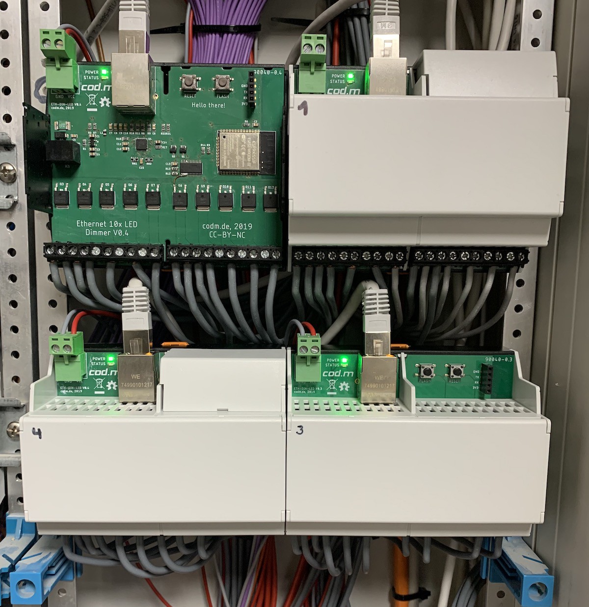
    After fixing this, handling the ESP32 exceptions better, refining the I2C pull-up's and meassuring the i2c bus for stability, we could move on to our first real-world test. Currently we drive up to 40 channels with 24V LED's with four dimmers over UDP without any problem.

    We've built a custom mqtt-adaptor to talk to the dimmer via node-red and get some status information back to display it on a dashboard.
    This functionality will be integrated into the dimmer itself as soon as whe have time to implement it. All different communication path's (UDP, HTTP, MQTT) will be selectable from the dimmer's webinterface.

    Currently the speed parameter is not working so well - next step here is to implement propper timing to be able to use miliseconds for this parameters.
    The different dimming curves look stunning with smoth transitions, of course depending on the LED's.

    For a test we've also built https://esphome.io/ to run on the hardware - worked after getting the configuration right, as the output enable of the PCA9685 is wired to a GPIO.

    I'll leave you guys with a photo :-)
    Feel free comment in any way.

    Cheers,
    Patrik

  • Getting the first version going

    Patrik Mayer08/19/2019 at 09:19 5 comments

    Finally the Phoenix Contact cases arrived. As they have different sized openings on the top and on the bottom side, they are not off the shelf parts and needed 6 weeks to get here.


    We also finished the first software version which will have no webinterface, sadly. But for the start it's UDP protocoll is completely compatible to our DMX bridge, with an addition for a high resolution command to dim the whole 12bit. Also dimcurves are implemented, so that you can decide how your input is layed out to the brightness of each channel.

    Valid inputs are 0-100%, 0-255 (8bit) and of course 0-4095 (12bit).

    For future software releases there will be an webinterface and mqtt support.

    What else do we need?

View all 3 project logs

Enjoy this project?

Share

Discussions

D Khazz wrote 12/01/2024 at 06:09 point

Any plans to share the schematic for this board?

  Are you sure? yes | no

xzacharm wrote 04/29/2023 at 19:41 point

Hello, this project looks like a match for my home automation. I am looking for a solution to dim my LED lights in house and no valid option i was able to find. Is this still going? Any chance to get it?

  Are you sure? yes | no

vstonkus wrote 10/08/2021 at 19:53 point

The project looks very close to what I’m looking for my new house. Inputs are mandatory to me for tcp/ip resiliency and low latency. In worst case I could hack them in myself. I’m interested in hardware. Most likely I would do custom software anyway.

Is the project still going?

  Are you sure? yes | no

Patrik Mayer wrote 11/29/2021 at 13:18 point

Sorry for the late reply. Yes, it is.

Currently in negotiations to do the CE part not in-house as we have too much work currently.

  Are you sure? yes | no

vstonkus wrote 11/29/2021 at 16:00 point

Thanks for the response!Any ETA? I will need a solution in few months, so would be good to know if it is worth the wait or look for alternatives. Will it have wired inputs option available? I will need ~8 units. Any estimate on what the price will be?

  Are you sure? yes | no

Patrik Mayer wrote 11/29/2021 at 16:06 point

@vstonkus: Check you inbox.

  Are you sure? yes | no

Ben Jones wrote 03/15/2021 at 09:18 point

Great looking project, is it still in development? I would be very interested to buy at least one unit for testing, with a view to getting a whole house lot! 

  Are you sure? yes | no

Constantinos wrote 12/02/2020 at 21:04 point

Hi Patrik!

Very nice project indeed!

I agree with Emanuele's proposal, it would be great if you had inputs.

Even with out the inputs I am also interested in this. I need around 3 devices, when available, please update us.

:)

Constantinos

  Are you sure? yes | no

Emanuele Tessore wrote 08/31/2019 at 12:11 point

Hi, just an idea: what about adding 10 inputs so that we can hook a switch for controlling the unit in case of a tcp\ip outage?

here's a real world example:
- a dining room has 10 led lamps
- 10 24vdc lines go from the lamps on an electrical box
- 10 24vdc lines go from the switches to the same electrical box
- the unit is placed in such box
now i can hook the switch to the unit and control the lamps by pressing the switches even if the home assistant or mqtt broker is not available

Thous inputs can be GPIO (if they are still available) or some i\o expander like the mcp23017 (which is supported by esphome https://esphome.io/components/mcp23017.html). It whould be great if they can be opto-coupled just for safety. The simple version is just a pin connector routed from the currently unused GPIOs, in particular the one taking care of i2c communication, and a daughter board or an external unit.

Cheers! 

  Are you sure? yes | no

Emanuele Tessore wrote 01/08/2020 at 09:08 point

up :)

  Are you sure? yes | no

Emanuele Tessore wrote 07/20/2019 at 16:56 point

Very nice project, perfect for my new home lighting system!

Any idea of the first batch availability and msrp?

Will it be capable of driving 48V leds (stretching the hexfet Vdss of 55V)?

cheers!

  Are you sure? yes | no

Patrik Mayer wrote 07/22/2019 at 12:49 point

Hey Emanuele,

first production batch is planed for later this year. Hopefully in 1-2 month.
Currently our input DC-DC converter can handle 7-36V for the electronics. The LED outputs are grounddriven, thus you may have a higher supply voltage for the LED's. I've not tested this though...

Cheers!

  Are you sure? yes | no

Emanuele Tessore wrote 07/22/2019 at 19:27 point

Good to know, thank you.

Let me know if you have a pre\early production batch for testing. 

Thank you! Cheers!

  Are you sure? yes | no

Similar Projects

Does this project spark your interest?

Become a member to follow this project and never miss any updates