Credit goes to our 3rd year group students:
Jamie-lee Thompson
Rohan Tangri
Zheyuan Li
Shiwei Liu
Zengrui Huang
Kosidinna Umeigbo
With the support of Simon Merrett from Remap UK
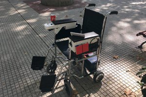
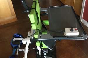
First prototype of an open kit to bring electric drive to any existing wheelchair for cheap (and -hopefully- safe)
To make the experience fit your profile, pick a username and tell us what interests you.
We found and based on your interests.
Credit goes to our 3rd year group students:
Jamie-lee Thompson
Rohan Tangri
Zheyuan Li
Shiwei Liu
Zengrui Huang
Kosidinna Umeigbo
With the support of Simon Merrett from Remap UK
Control.aiaMIT App Inventor project for the Android app that controls the wheelchair from the phoneaia - 161.23 kB - 07/24/2019 at 09:16 |
|
|
WHEELS Technical Report.pdfThis is the project report the students wrote. It describes most of the details of the project (including a project log) except for the PCB design and the final layout.Adobe Portable Document Format - 2.83 MB - 07/15/2019 at 08:44 |
|
|
wheelchair1.inoCurrent version of the Arduino program that does the magic. The program reads the inputs from the analogue joystick and translates that into a direction+PWM signal to command each motor driver. There's an algorithm in place that processes the joysetick input and limits the jerk to make the ride smooth. The program also takes an optional BLE connection that can be used to remote-control the wheelchair.x-arduino - 15.52 kB - 07/15/2019 at 08:42 |
|
|
solvespace_models.zip3d models of the 3d-printed parts I used to hold the battery in the wheelchair, to hold the PCBs inside the connection box and to hold the connection box sitting on top of the battery. The models can be opened using SOLVESPACE cad.Zip Archive - 125.59 kB - 07/15/2019 at 08:40 |
|
|
Joystick_board.zipKicad files of the board where the analogue joystick, the buttons and the indicator leds are wiredZip Archive - 2.43 MB - 07/15/2019 at 08:40 |
|
|
One of the features of the electric wheelchair prototype is that it has a BRF8001 module that enabled remote control from the phone. I never saw the point of this feature and actual wheelchair users told me this was a no go but arguably this feature made an impression when the students presented the project.
I wanted to write a few lines about how this works in the current prototype and share the source for an application that enables the control from a mobile phone. Adafruit's website has a ton of information about how the BLE module can be used from Arduino and it is pretty straightforward. Specifically, there's a page that gives the details that need to be known in order to use the module as a UART: https://learn.adafruit.com/getting-started-with-the-nrf8001-bluefruit-le-breakout/adding-app-support
I put together a basic application using MIT's App Inventor that enables you to connect your phone to the BLE module and use a basic on-screen joystick to control the wheelchair. The position of the joystick is sent to the wheelchair as a string with two signed integers in the range between -100 and 100 for the X and Y axis separated by a comma. For example: "0,0" for the resting position and "0,100" for forward motion at full speed.
I never thought I'd share source code as a picture but it makes sense when you program using scratch. Here's the screen layout of the app:
And here are the blocks that make this work:
The actual app inventor project file can be found in the files section of the project page (a .aia file). The code is pretty straightforward: you press "scan" to get a list of nearby BLE devices. You then choose the UART in the list and press "connect". Once the status reads as "Connected" you can start moving the joystick and the app will send the joystick position to the wheelchair controller.
I noticed when testing this on my phone that the mobile app would sometimes send a ton of messages to the BLE if you moved the on-screen joystick too often. I suspect that this could cause some headaches to the NRF8001, therefore I used a timer to limit how often messages can be passed from the phone to the mobile. The update rate is of 10ms, the solution is not very elegant but it is good enough to demonstrate how this works. If this was to be implemented in a real electric wheelchair for people to use, things would have to be designed to be secure (e.g. some pairing process involved) and able to handle potential attacks.
One of the interesting parts of the project was the analysis and the design of a controller that would translate the joystick command into the command that is sent to the motor driver. The goal of this controller is to act as a filter and avoid sudden movements of the wheelchair that would cause discomfort to those riding it. I posted some work on this topic a couple of years ago and it can be found here: https://hackaday.io/project/21343-control-of-a-vehicle-with-two-driving-wheels
The controller that is implemented in the current wheelchair prototype is a follow-up of the work above. The details of this new controller can be found in the student report in the Files section of this project page. The prototype features a "jerk limiter" that makes the acceleration (or the force) ramp up smoothly. This feature can be enabled and disabled by pressing one of the buttons of the joystick controller. The effectiveness of this feature became pretty clear when testing the 1st fully-working prototype, where components where held -literally- by gravity on the wheelchair seat. If the jerk limit was disabled the components would move around the seat unless the person controlling the joystick paid great attention to keep acceleration mild and smooth.
I did a quick measurement of the current drawn by the motor drivers for a full forward acceleration command with and without the jerk limiting starting from rest and this is what I got:
The plot is horrendous because I took a picture with my phone and supervised the results of two tests but it shows the effect of the jerk limiter: with no limiter, current (or torque) goes from 0 to maximum in less than a second, whereas with the jerk limiter in place is transitions between 0 and full in about 2 seconds. This of course can be tuned but the point is that the algorithm is implemented and ready to be used.
The are two further functionalities in place that are worth noting: one is that the controller uses a dead-zone around 0 speed to make sure the motor driver doesn't try to move at very low speed when the joystick is in its resting position if the joystick is not well calibrated. A second feature is a "cruise control" that keeps the forward speed constant and allows the person driving the wheelchair to give only "left-right" commands. This feature is quite well implemented and is disabled instantaneously whenever the joystick is pulled backwards or the button is pressed again.
The Joystick board is pretty simple, it contains 4 LEDs, 3 push buttons and a 2 axis joystick that we got from a Parallax board (https://uk.rs-online.com/web/p/products/7813064/)
The board has two connectors where two (repurposed) ethernet cables are wired. In a future design I would rather remove the LEDs and reduce the number of switches to use a single ethernet cable or perhaps a simple three wire cable but at the moment I didn't want to do any major redesign of the circuits.
The PCB was designed to be 2-layer and milled using our Bantam Tools Desktop CNC. This has some implications: I avoid connecting to through-hole legs from both sides of the board and make bias be far from components to simplify soldering. Still, these circuits are pretty simple and the board was very easy to route.
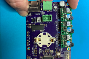
The motor controller board takes a DC voltage straight from the battery to feed an Arduino board that reads the inputs from the joystick board and sends a PWM signal plus a direction signal to two DC motor drivers. The board also has a socket where we connect an Adafruit nrf8001 BLE module (https://www.adafruit.com/product/1697). This module is optional and I'm very skeptical about the interest to enable bluetooth control in a real wheelchair because of the safety implications but it was good fun to be able to radio-control the wheelchair for testing purposes.
The motor controller board can also measure the voltage of the battery. At present there's no BMS for the battery and no software in place to cut off the power when the battery runs low but this is available for future use.
Once again, the PCB was designed for milling:
I'm not expert designing PCB layouts but I did my best to keep loops to a minimum and use decent trace widths. None of this is really high frequency, therefore I hope the board does the trick fairly well. I also relied on the decoupling capacitors of the Arduino and the bluetooth board but there's plenty of room to add other stuff in future iterations of this design.
A few other pictures:
As you can see, I had chosen a small case for the joystick and in the end I struggled to fit everything inside. I also had to remove a connector to be able to close the box. Ugly as it looks, in fact things weren't under heavy compression and it is perfectly ok to open and close the box any time:
The controller board sits on top of the battery in the back. It is relatively lightweight and I couldn't find a better way to hold it. This prototype is only for indoor use, the motors, the battery and all enclosures have relatively low IP rating. It is good enough to withstand dust and light vibration from normal use indoors but I wouldn't expose it to rain or any outdoors conditions.
A neat thing about the design is that if we remove the bluetooth board, we leave a big socket in place with access to the SPI pins of the microcontroller that can be used to connect other hardware for future expansion as well.
Hi, I've just uploaded all material I have from the project without spending any time documenting it properly. Still, in the files section you will find the report our 3rd year group project students wrote.
Credit for this report, the design of the wheelchair and the Arduino code that makes it run goes to the following people:
Jamie-lee Thompson
Rohan Tangri
Zheyuan Li
Shiwei Liu
Zengrui Huang
Kosidinna Umeigbo
Well done!
My role as their supervisor was to oversea how the project ran. This project was done in a real hurry in about a month time. I spent a few days later on to turn their perfboard circuits into PCBs and give them nice enclosures so that we can keep the wheelchair for next year.
I will try to find time to post a couple more messages here to describe how this work and what we think we should do in the future to continue the design of the wheelchair.
Huge thanks to Simon Merrett for approaching me back in 2017 and being happy to support and advice our students.
Create an account to leave a comment. Already have an account? Log In.
Thanks! I didn't realize they mentioned the project in their email.
There will be a follow-up as a final year project next academic year. I've already started to advertise it. I hope I'll get a good and highly motivated student again.
Thanks for your help, I hope we'll be able to show something actually useful and easy to use by many people soon
sumting a seen a while back
https://www.youtube.com/watch?v=eG9q6iHF_bI
https://www.youtube.com/watch?v=40VWQc9agfU
https://www.youtube.com/watch?v=oWTA2BOz5SQ
https://www.youtube.com/watch?v=Dwh9i5mEaYc
these cordless drills are ready made , probably have a year waranty if youre sneaky about its use are realy light and adaptable , they allso have everything you need build intoo them
Thanks. It is true that they are cheap and they come with many useful features; however, it is hard to turn them into something that is enough user friendly.
I don't like the idea of using a electromechanical contraption to press the drill trigger. A while ago I hacked a drill (goodbye warranty) to be able to have proper electric control while still being able to use it as a drill. I wasn't happy with the result (it took a lot of time and skills and it was hard to replicate).
I'd like to be able to offer proper speed control and safety. My idea is to combine inexpensive brushless motors with an adaptable coupling for different wheel shapes.
Become a member to follow this project and never miss any updates

 elmameto
 Alvaro Ferrán Cifuentes
 AVR
AVR
 Phil Malone
Awesome! Congrats on the whole project guys, oh and making it into the HaD.io weekly email!