 Carbon
I was using the end off an Amazon USB cable and it looks like the internal wire colors were swapped. Out of ideas last week, I swapped the data lines and the chip enumerated successfully!
Now that I knew that it worked, I figured it was a good time to do a board revision:
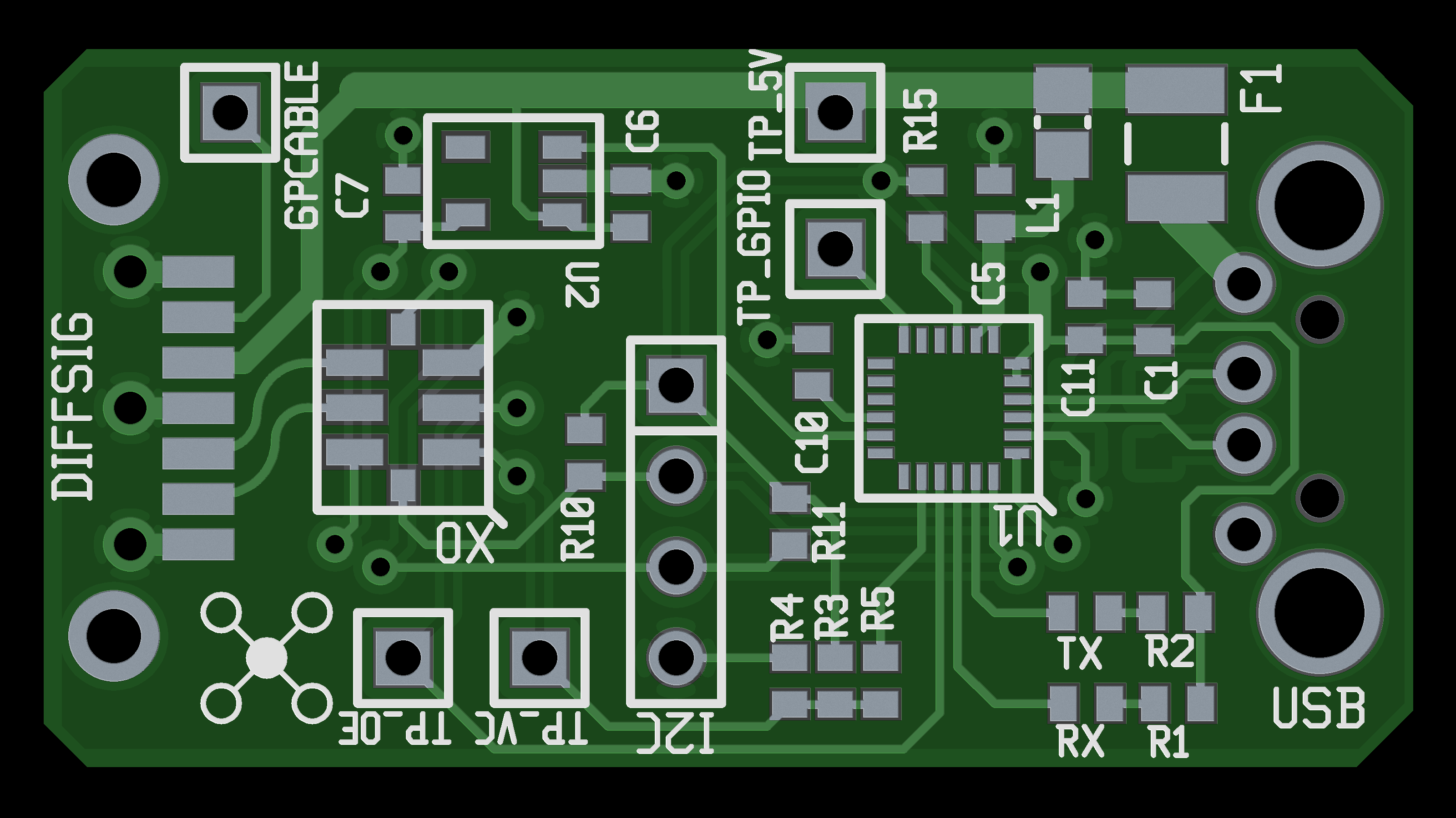
You might notice that the Rev B board is shorter than the Rev A board. I moved the TVS diode array to the opposite side - the wiring between it and the CP2112 was a tad frustrating and taking up a bunch of space. The XO footprint is the smaller 3.2 mm by 5 mm variant which should match the parts I have.
I also added a footprint for a PCB mount USB-A male connector. It's what I originally intended to do, and it's a lot cleaner than having the board at the end of a cable.
The only major circuit difference is that the SATA port pins have changed - check out the schematic in the gallery for details.
Boards have been ordered from OSH Park. I took down the link to the Rev A boards because they were obsolete - I wish there was a way to set up the sharing so it wouldn't expose the the raw Gerber files for download.
Discussions
Become a Hackaday.io Member
Create an account to leave a comment. Already have an account? Log In.