 Andrey V
SCHEMATIC
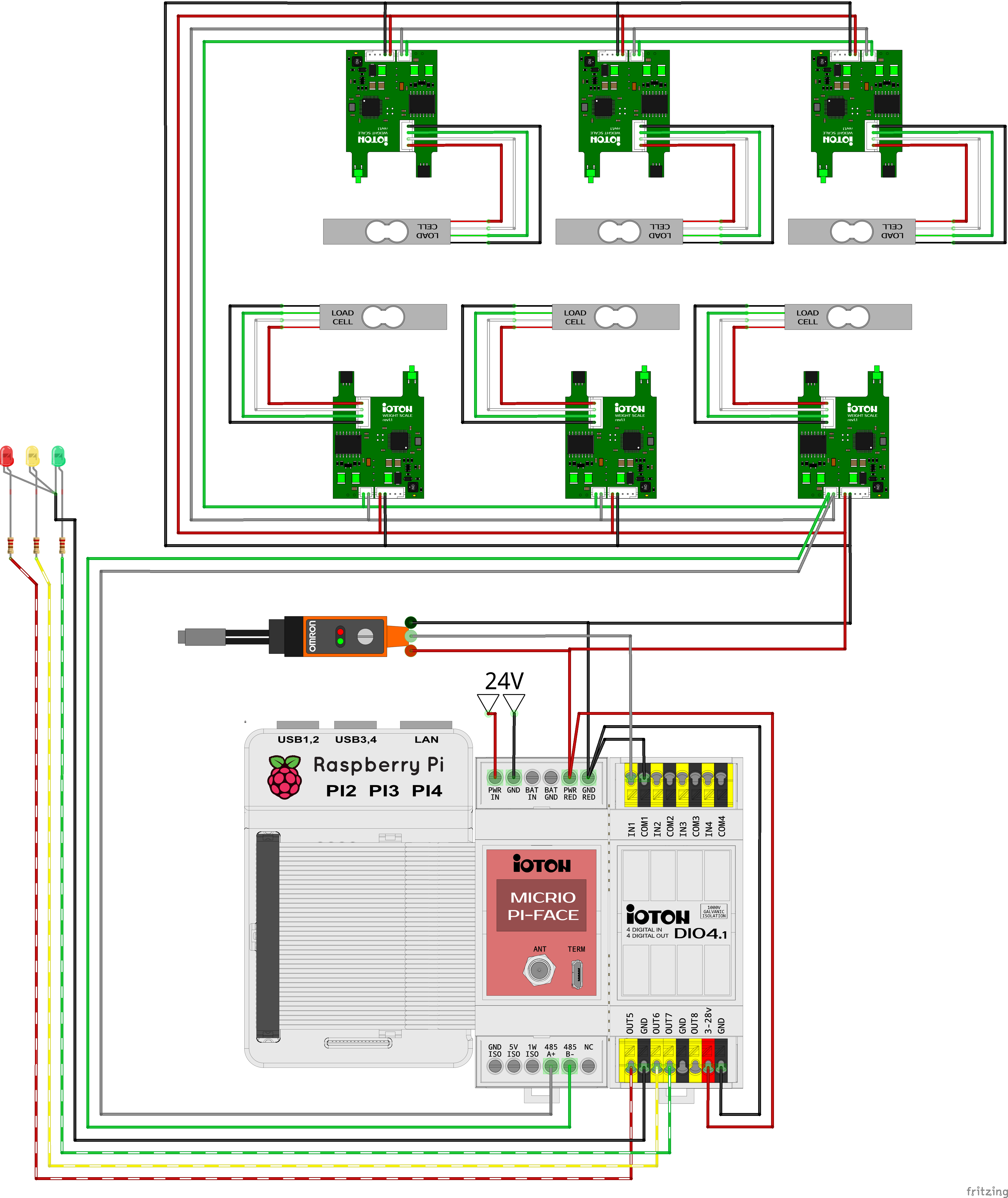
The schematic of my test setup is quite simple:
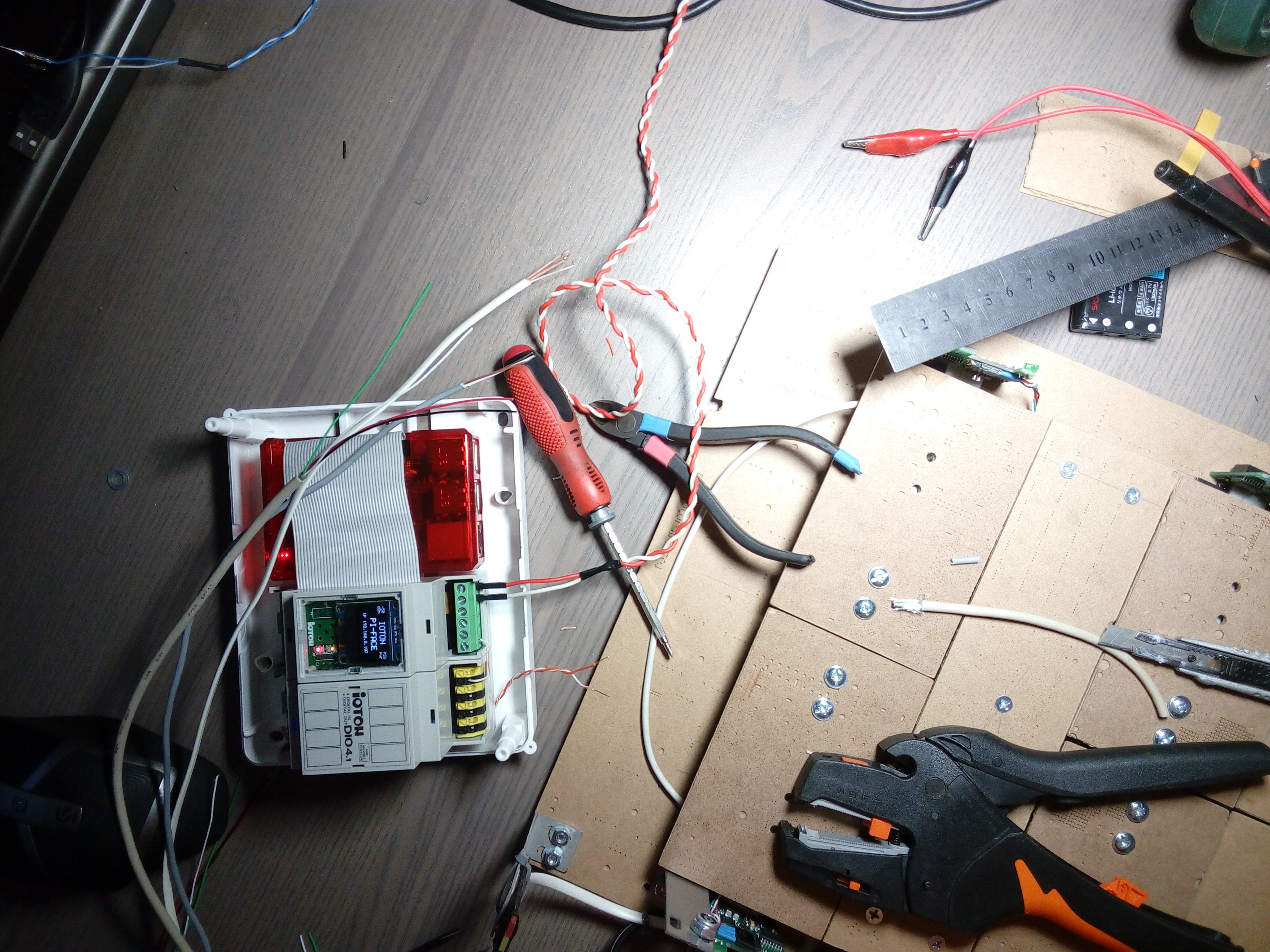
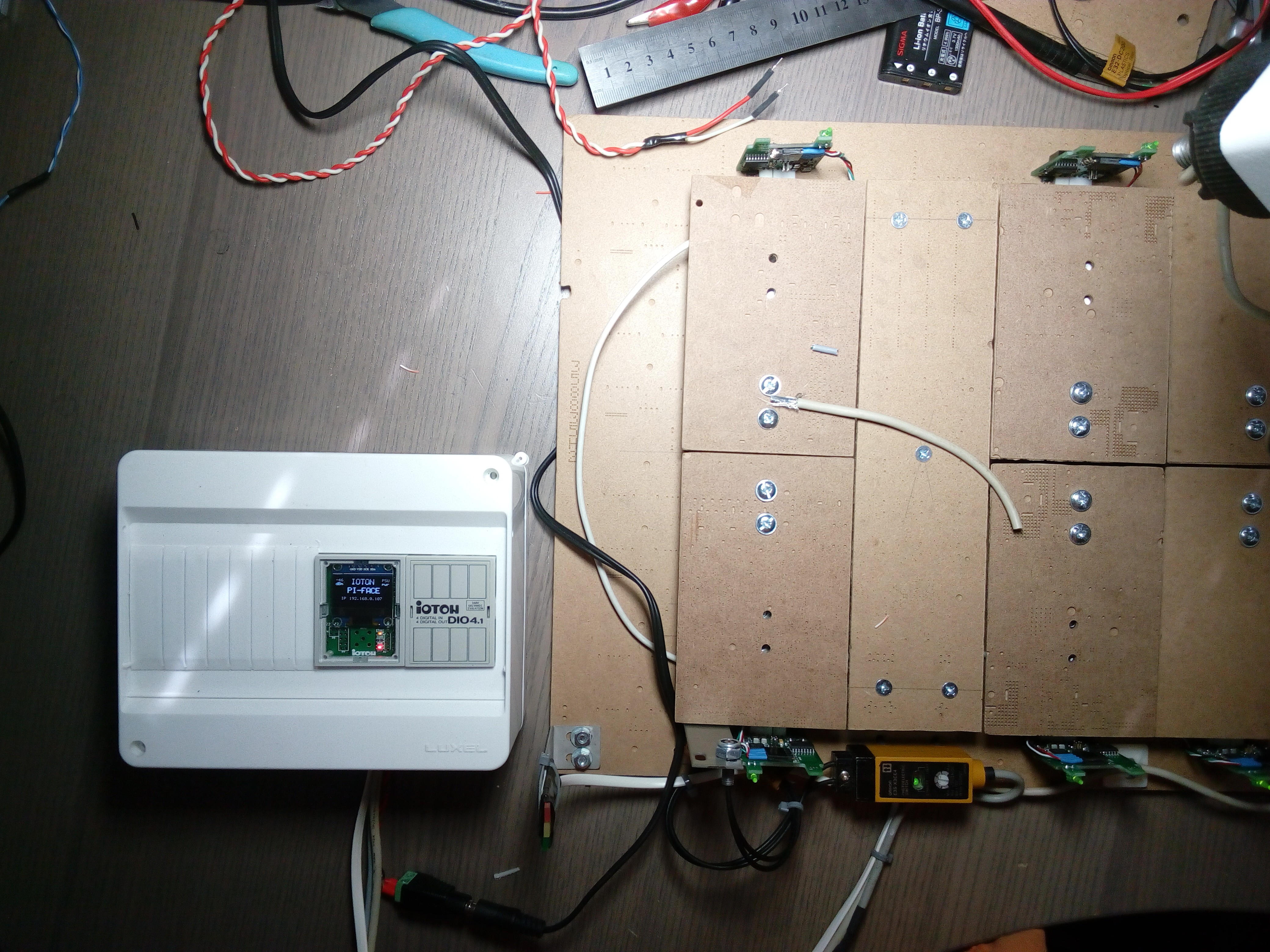
WIRING
It's also simple, I did it in around 30 minutes. It's no problem to connect cables to the powered device, it's only 24V and has protection and galvanic isolation for any inputs, outputs and data lines (like RS485 PHY).
Cables connection:
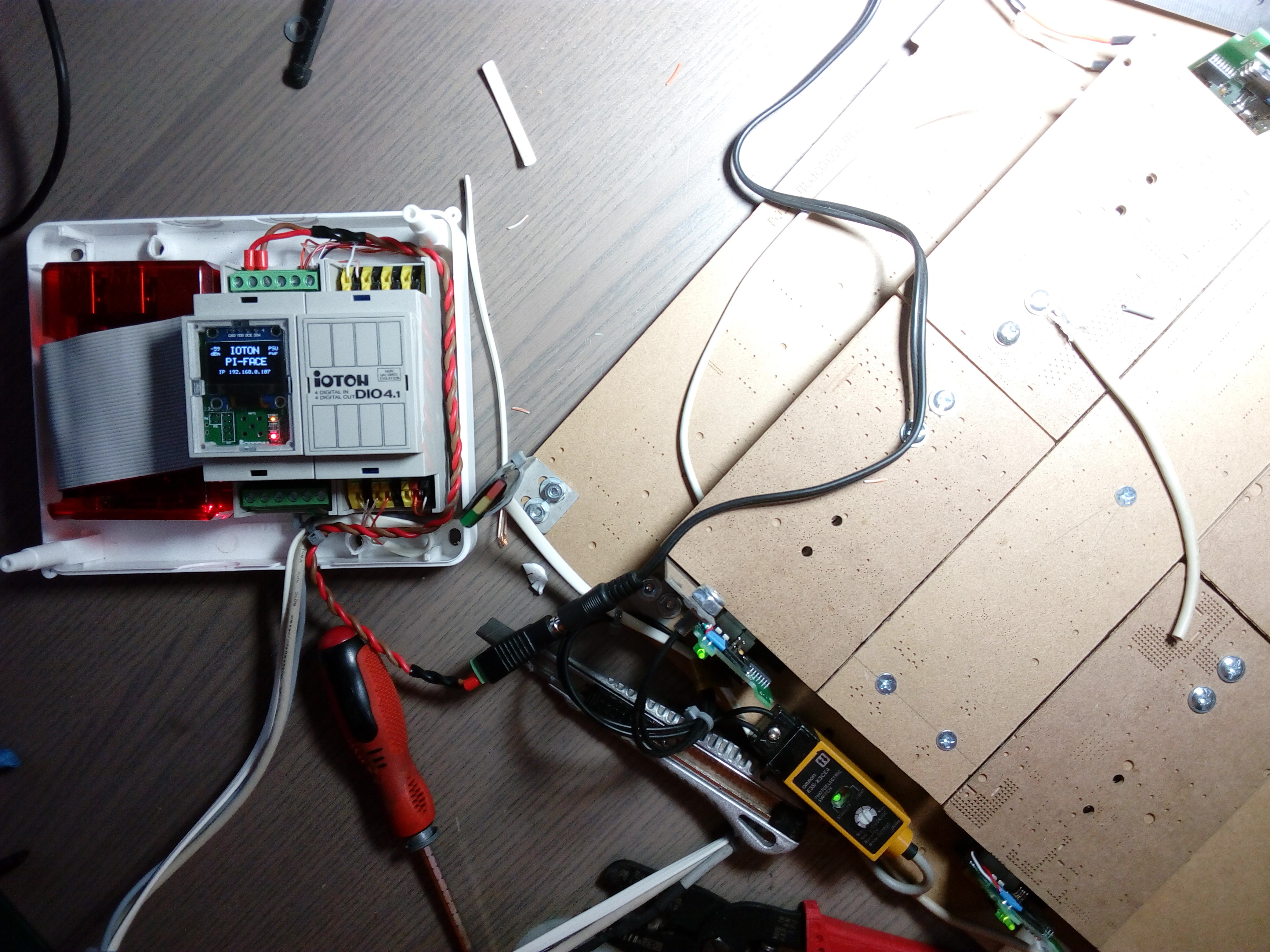
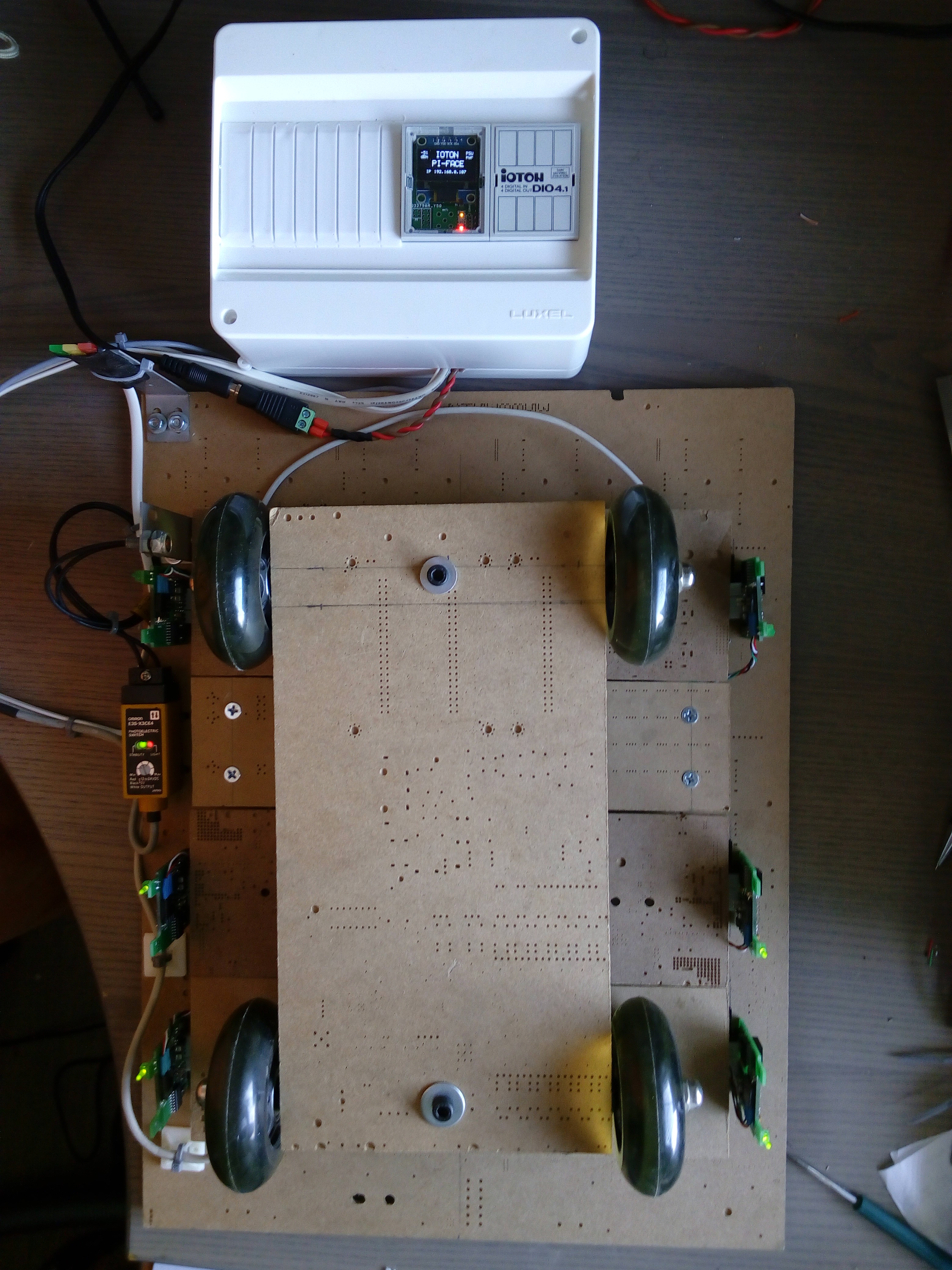
Put covers in place:
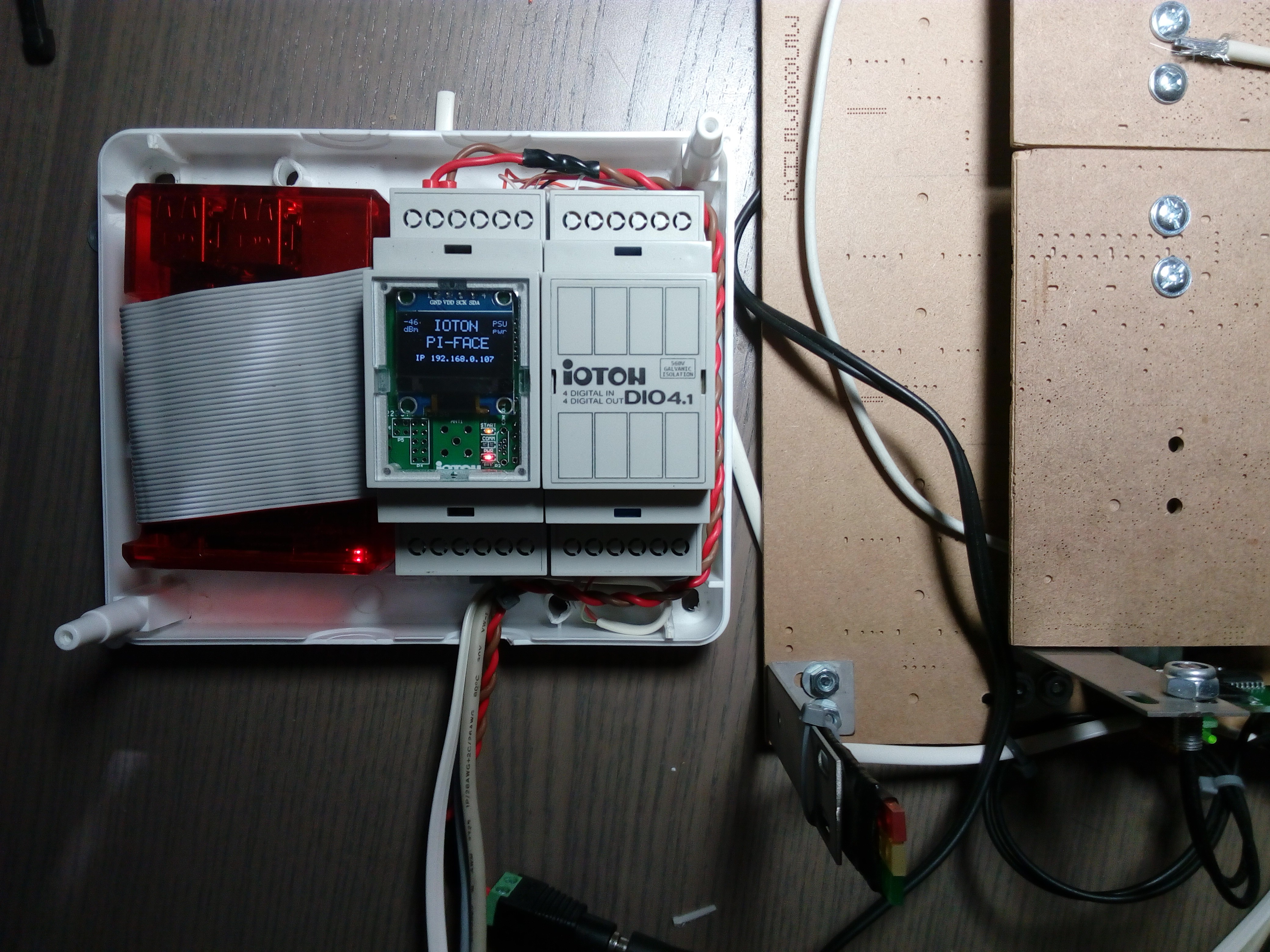
Ready setup looks like this:
Now it's time to create a user interface and do some programming.....
Discussions
Become a Hackaday.io Member
Create an account to leave a comment. Already have an account? Log In.
Welldne! they way they have connected these wires to make it workable. Such programming must be publicized so that others can also know about it because I get outstanding work at https://edubirdie.org/ site. I really appreciate them and this blog for doing the great work on such technical issues and make it visible for us.
Are you sure? yes | no