Before going on with the electronics, I'd like to write a bit about the most painful and stressful part of building a product: the enclosure.
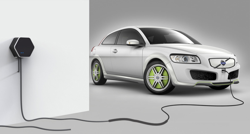
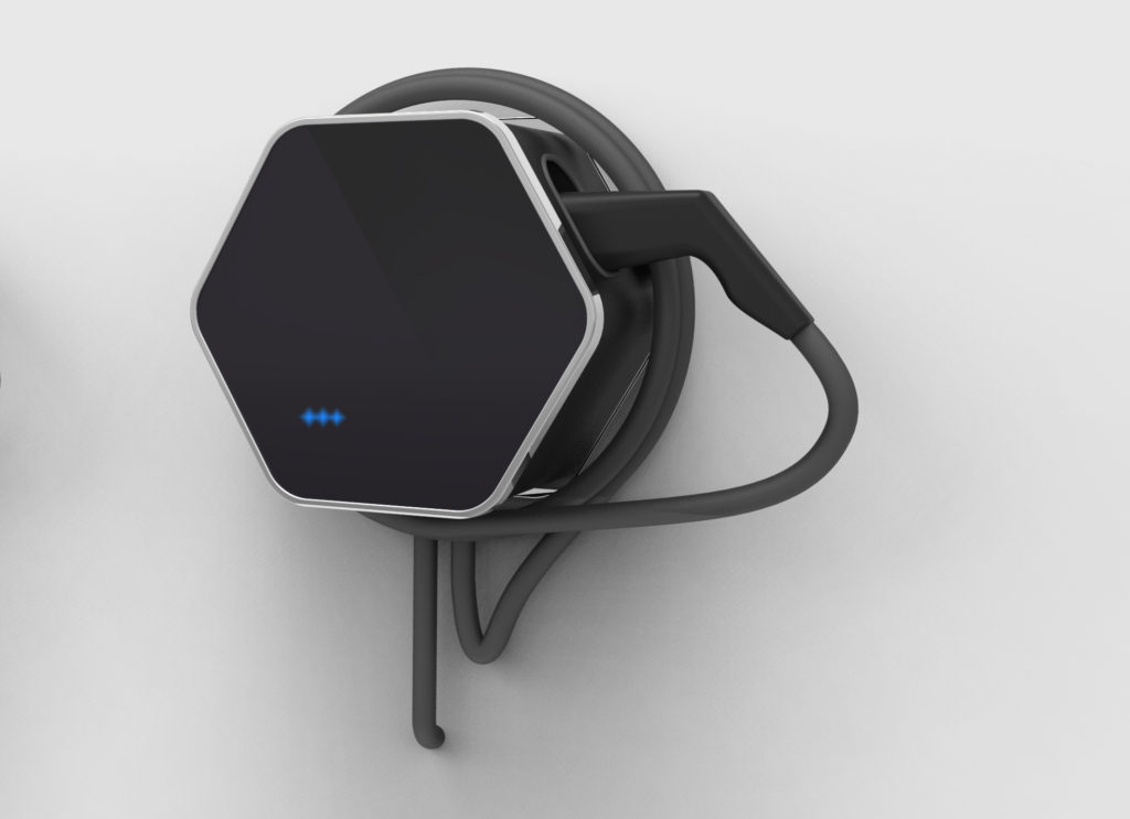
It all started when we pitched the idea to a friend who's a product designer and asked her to come up with some designs. She prepared a few renders, and we ended up going for a nice hexagon-shaped design:
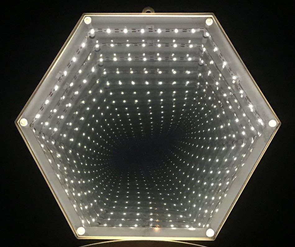
And on top of that, I wanted to add an infinite mirror effect to the cover, with WS2812 RGB LEDs to give users feedback about the status of the charge, like this:
Other than a great looking, we wanted our enclosure to be water resistant and very strong to resist outdoor weather conditions. Charging stations are typically abused, so we need to make sure our product is rock solid to stand the test of the time.
Great, we have a design idea! Now we just have to build it, starting from simple prototypes to check sizes and proportions. So here starts the journey, with the first fail:
Prototype #1: FDM 3D printed case [fail]
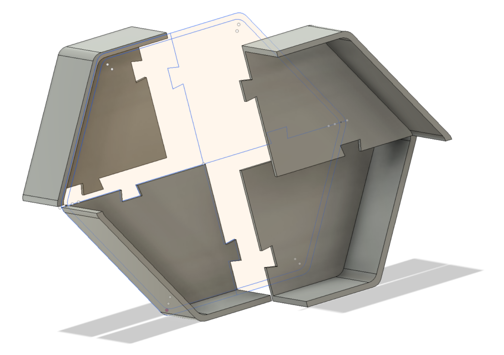
I don't have a picture of the pieces that I printed, but it turns out it's pretty difficult to print big pieces that fit together perfectly, while pushing the limits of a humble Tevo Tarantula 3D printer. I don't have much experience with Fusion 360, so don't get scared by the ugliness of the design. Long story short, a new solution was needed, so I thought I'd use both laser cutting and 3D printing:
Prototype #2: 3D printed corners and wood [WIN]
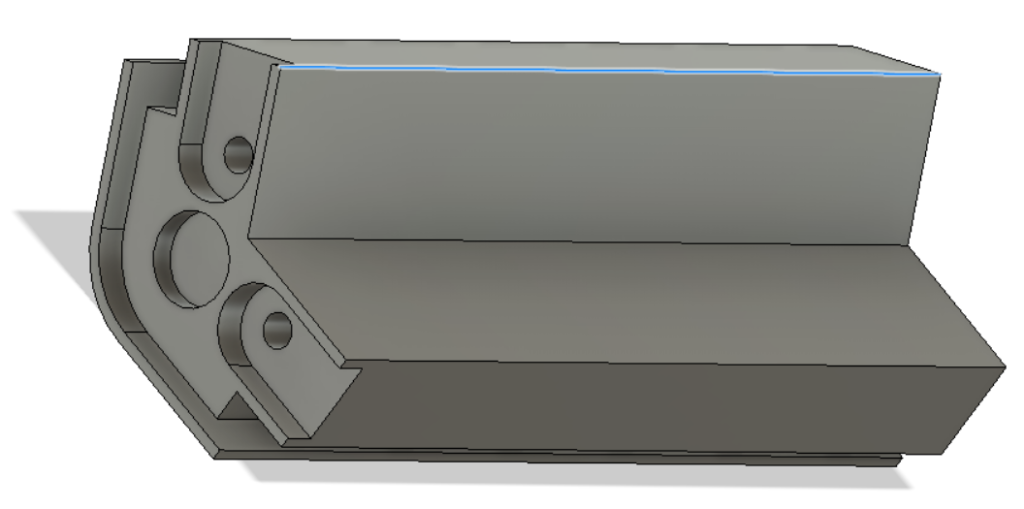
Here I 3D printed only the complex corners; everything else is cut from 2mm plywood. Mixing these rapid prototyping technology makes a lot of sense, as we could better work around the limits of the cheap 3D printer and use the laser cutter to its potential. The bottom is screwed into the pieces, and the sides are slid into the edge slots. On top there's a hole for magnets to hold the cover, and two U-shaped recesses for wood strips to hold everything together. Et voilà, the first prototype was born!
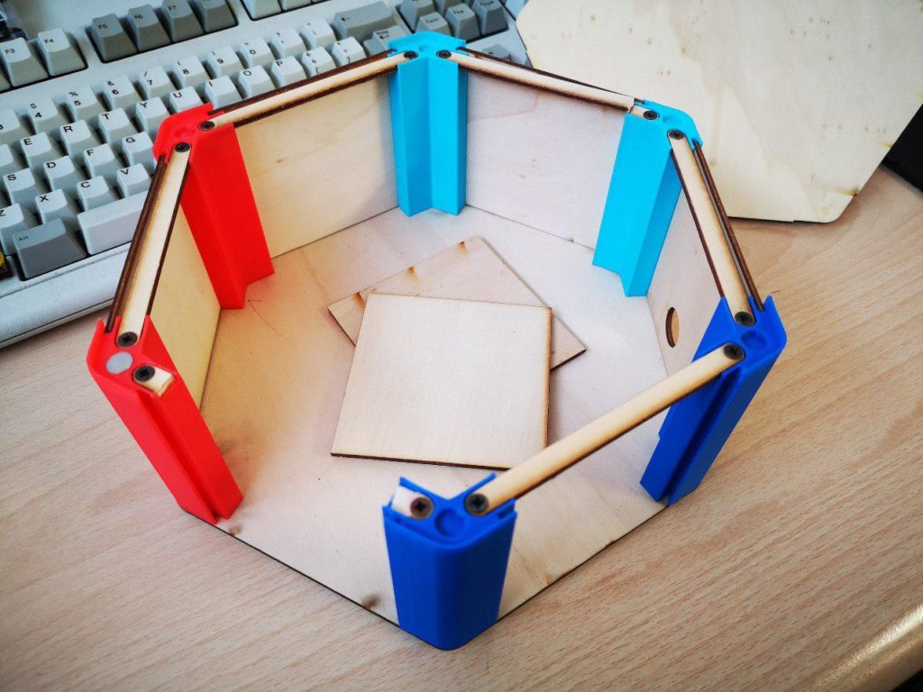
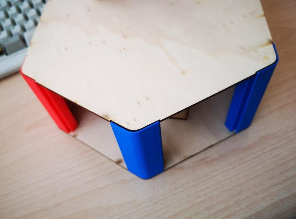
We could now hang it to a wall to see if the design makes sense, and test the size of some components. And you can make it too, here's the design!
With everything looking good, we now had to make the next step. But, as any maker with little-to-none experience in industrial manufacturing, we were scared as hell to commit to an extremely expensive plastic injection mold, so we approached Mentec, a company specialized in low-volume enclosures made of machined, folded and glued plastic. Their demo enclosures looked great at the fair where we met them, and I was pretty enthusiast about the potential of this solution. However...
Prototype #3: folded plastic housing [fail]
This seemed like a great idea, as despite the very high price for small quantities, we could use that to bootstrap production and fix bugs and then with the money made with the first sales invest in a proper injection mold. So we sent them our designs and drove to Munich for a meeting to define all the details.
We received the first prototypes about a month later, and we were quite disappointed. They didn't look nearly half as good as we imagined, despite the amazing manufacturing quality for an handcrafted product.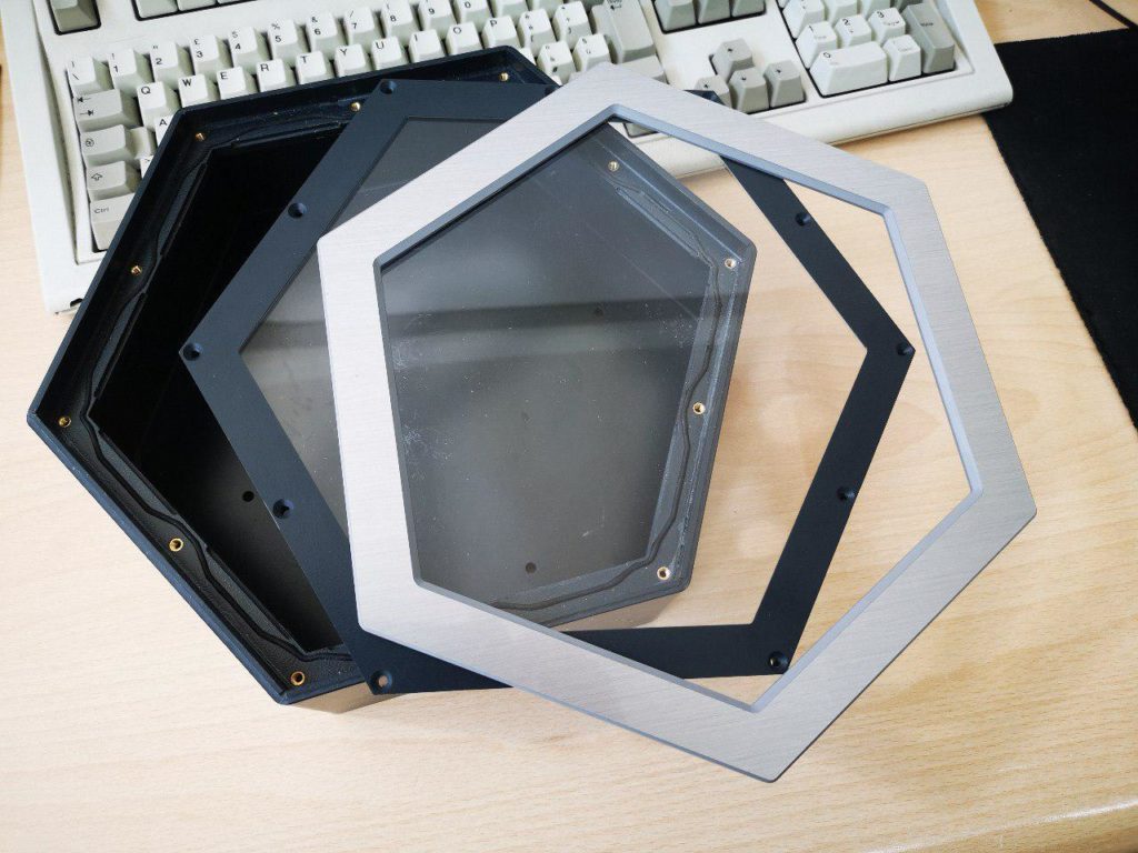
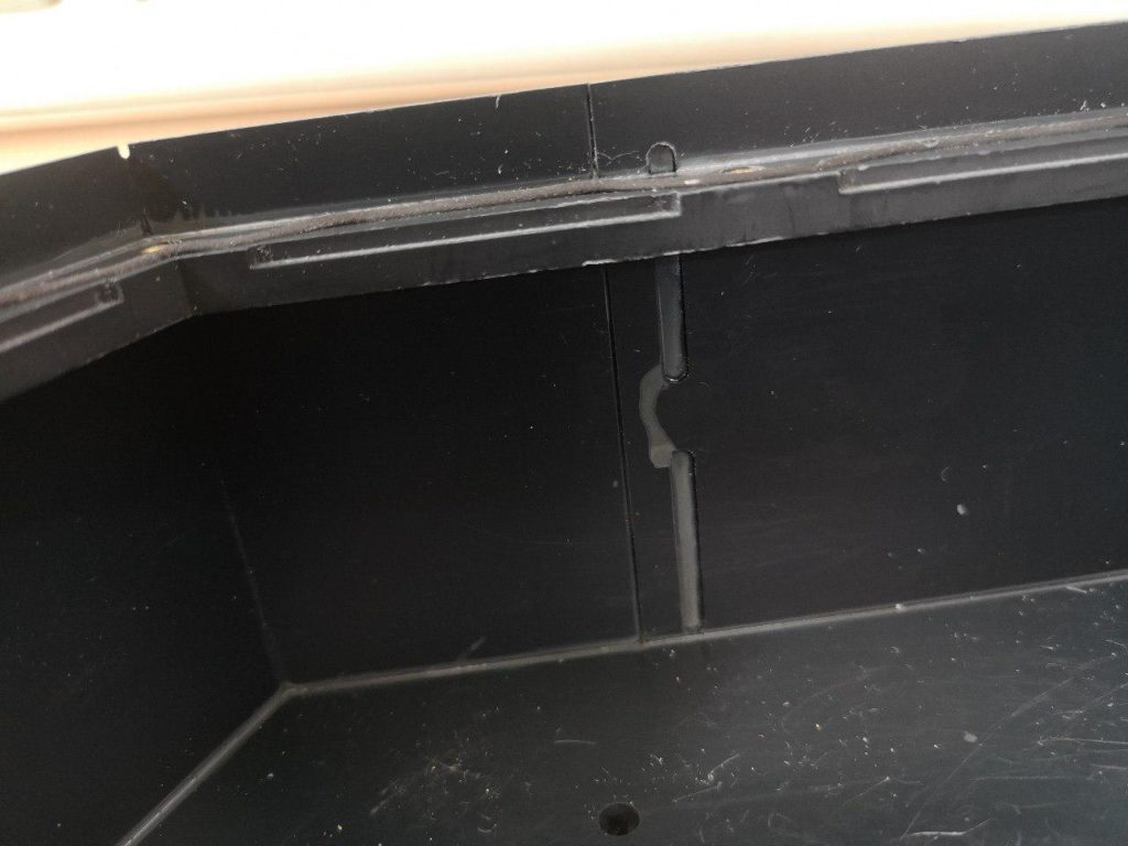
The box is formed by two strips of folded plastic shaped like \_/ and then glued together. Here you can see a detail of that joint, where they milled the strips and then glued them together through the holes inside:

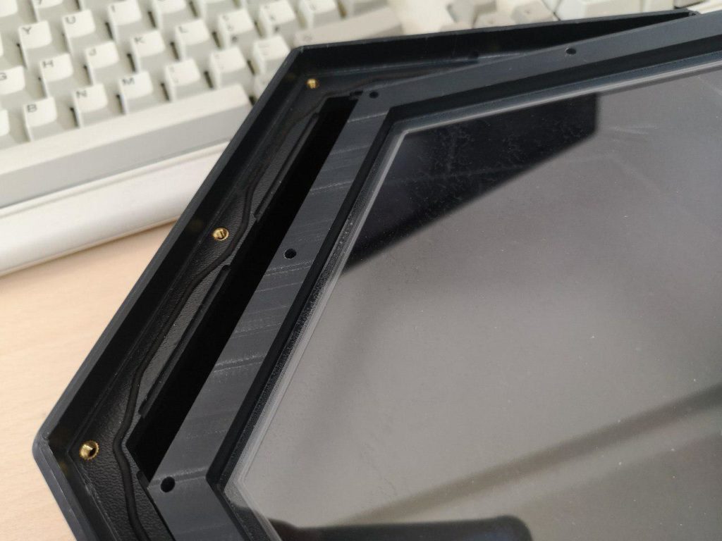
In the same way, the perimeter is milled at the right height to fit and glue the bottom sheet. Then a milled hexagon made of a thicker plastic is milled and glued to the upper part of the perimeter, with space for a neoprene gasket and threaded inserts. The front panel is made of a matching hexagon, with a glued transparent window to make the infinite-mirror and slots to fit the other piece of the mirror:
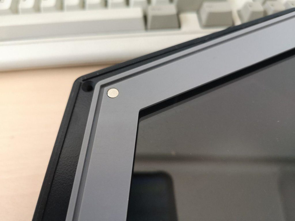
And finally we have the top bezel, made of a nicer plastic, with slots to mate with the edge underneath, and magnets to keep it attached to the screws:
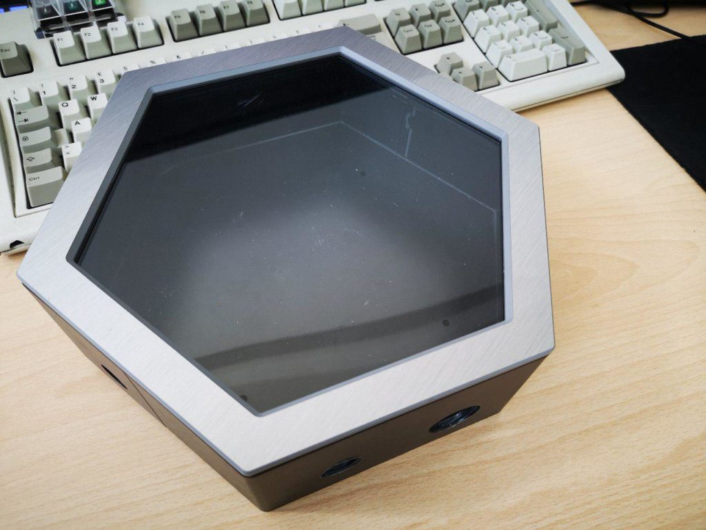
The end result is not even that bad, but it's too blocky/squared due to the nature of its construction.
Of course, we knew this solution was a compromise. We started looking at alternatives, but these enclosures at least allowed us to assemble some prototypes to validate the design. Here is a fully assembled prototype, with the electronics fitted inside the DIN box on the left:
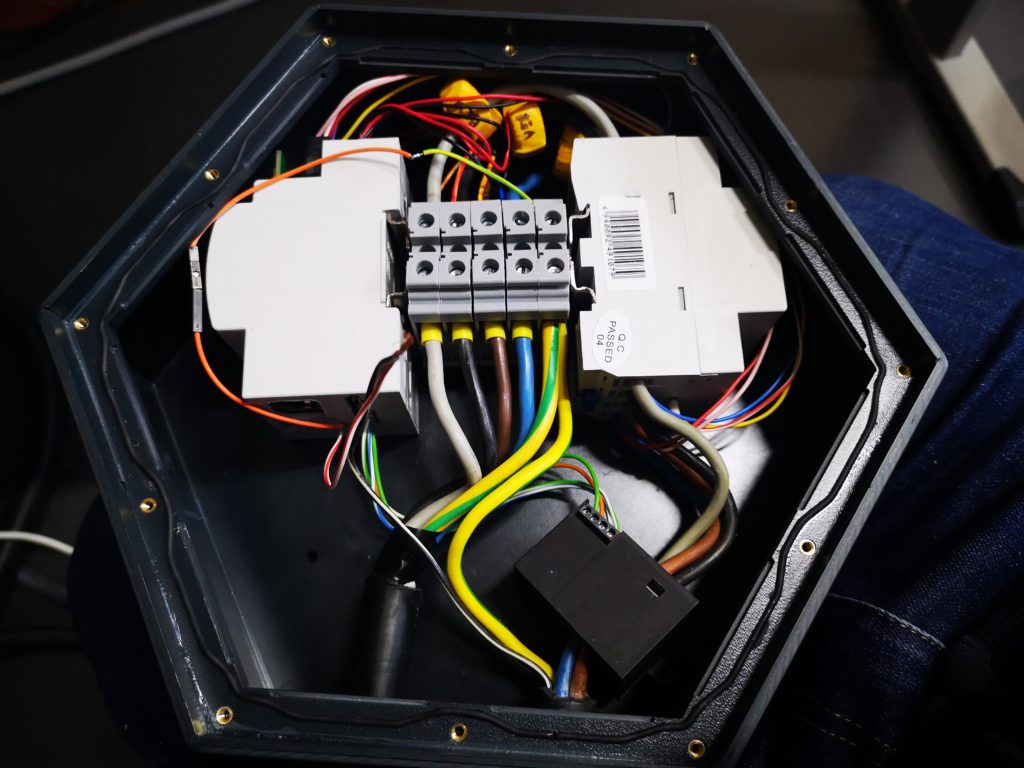
A lot of stuff was still missing, like a way to anchor everything to the base. As you may notice, the placement of the components was a bit unusual too: the idea was to lay the tallest components on their side to save space, especially as the front panel grew quite thick due to the infinite mirror thing. Then we would fold the DIN rail in a U shape and couple it with another rail to hold the screw terminals:
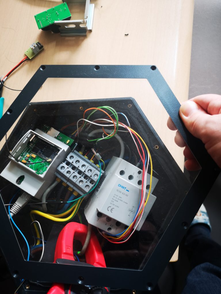
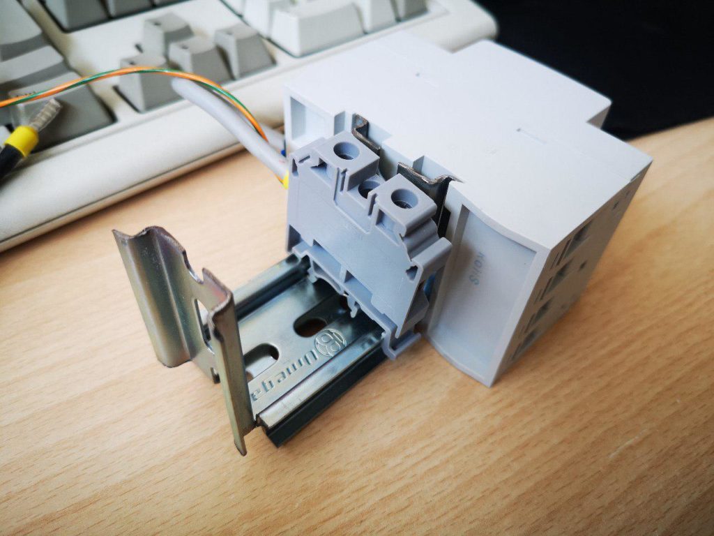 This seemed a great idea at first, but it became soon clear that all of these complications would come back to bite our asses in production. So we made the sensible choice and ditched the infinite mirror idea altogether, simplifying the design by placing all the components upright as they were meant to be. Here I'm testing the new possible layout:
We didn't win this battle, but we definitely learnt a lot. So we went back to the drawing board, and started exploring another crazy idea I had when I was playing with the 3D printer:
Idea #4: Aluminium extrusion [fail]
If you look back at the 3D printed corners, you can clearly see that they could easily be made by extrusion. I started looking into this really fascinating technology and indeed it turned out to be quite cheap and easy to manufacture. Here's a nice video explaining the process. We had a some options: first was, of course, to make a profile like the one I 3D printed. But then we would have to add metal sheets for all the sides, and machine each piece with holes for the bottom and fittings for the top and bottom covers. A die for this size would cost roughly 3000€, and the minimum quantity is always 1000kg of aluminium at about 3€ per kg.
A better option would be to extrude the complete perimeter, but hollow extrusions are super expensive, so the next best thing would be to extrude only half of it and join the two parts with screws; this would ensure robustness and provide an easy way to assemble the final product:
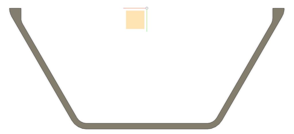
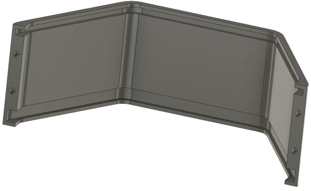
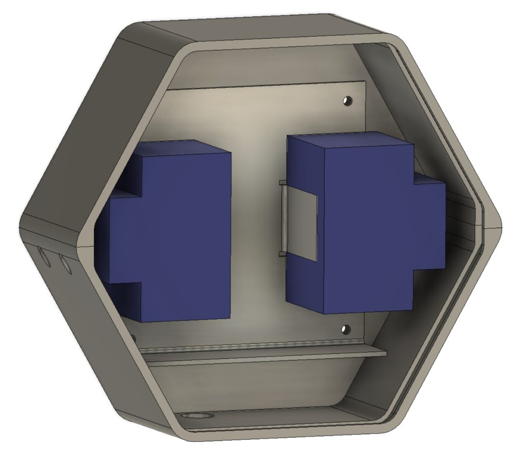 Unfortunately there are big drawbacks for this solution too. The back plate would be separated from the wall, but that can easily be solved with a machined (expensive) plate or some pressure-formed dimples if made with sheet steel. We were also worried about bad alignment of the two parts making an ugly visible seam. Despite the cheap extrusion, this method would require a lot of additional parts and machining, increasing the cost too much.
This final experience made it clear that we really needed to go all-in and invest in proper injection molding.
Idea #5: Zama injection [fail]
Looking around and telling our friends about our project, we ended up meeting a company making molds for metal injection, specifically for Zamac alloy. I didn't know much about that, but it turns out it's a great material! It's light, very strong, and more importantly it seems like its molds are cheaper than molds for plastic!
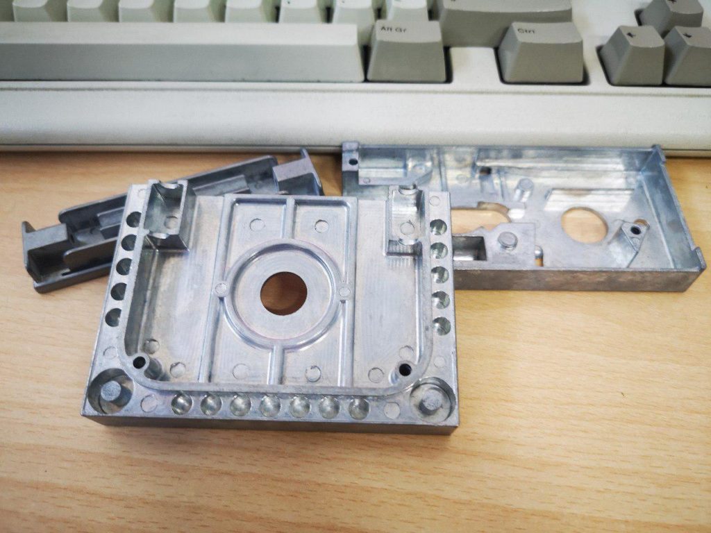 It's impressive the amount of detail you can get with this metal. We worked with the company to get our design made, but after working on the model they couldn't find an easy and cheap way to make the mold without introducing ugly artifacts from the injection points in user-visible areas. It's also not a great idea to build high voltage stuff inside a metal case, despite the good grounding and isolation. But my adventures with Zama are definitely not over, I'll find a way to use this material in a future project!
Final solution: plastic
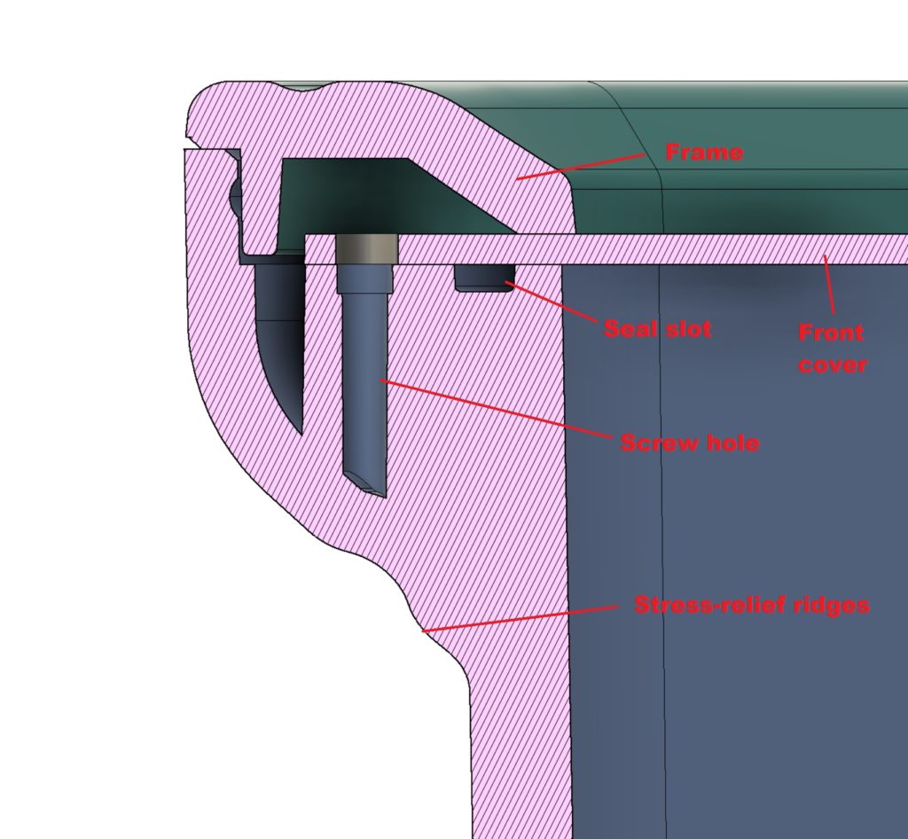
In the end, we had to fight the big monster anyway. But we got very lucky here: a friend pointed to a local company with a lot of experience in this field, Nercos. The very friendly owner spent a lot of time going through every detail and recommended a good consultant that helped us refine the design and prepare it for manufacture. There are some important details that need to be considered, like stress relief points in places where the plastic changes thickness to account for retraction while cooling. There are big constraints too, you have to imagine two separated coupled molds so you can't have undercuts unless you want to pay a lot of money for retractable supports. This is the reason why we didn't build the cable holes into the mold; at least for this first batch, we will drill them with a special fixture that I'm making (more on that when I finish it, it's quite embarrassing at the moment).
After some fiddling we got our first professionally 3D printed prototype:
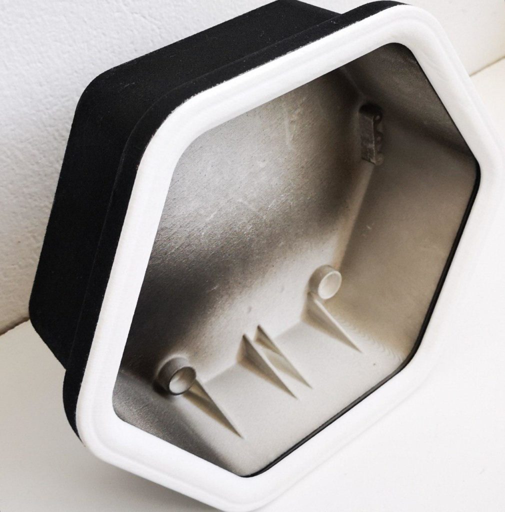
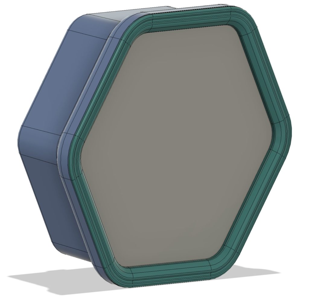
The enclosure will be made of three pieces; the sheet cover will be screwed into the base, with a neoprene ring seal all around, and the screws will be hidden by the top frame that is just snapped in:
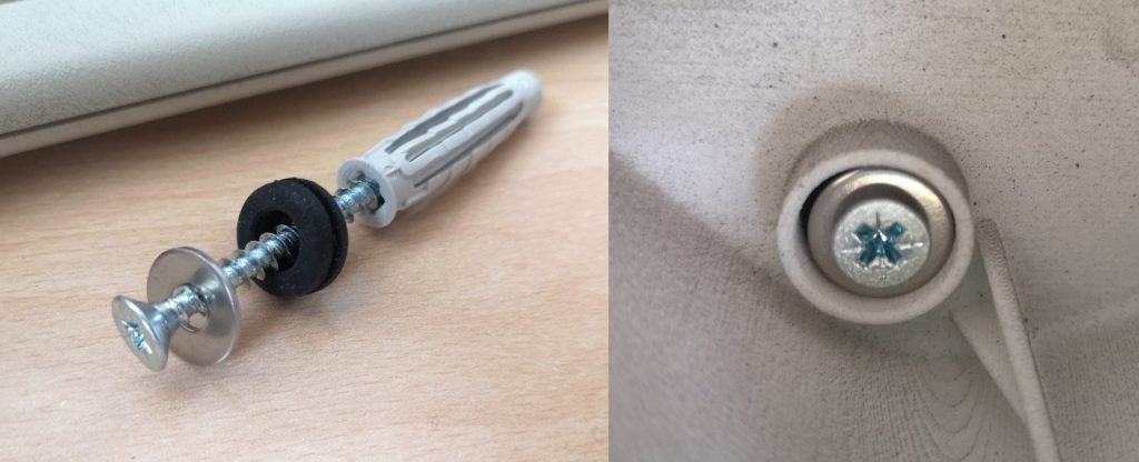
While the neoprene seal guarantees impermeability from the front, to avoid water ingress from the back we created slots on the plastic to snugly fit a rubber grommet compressed with a washer of the same size:
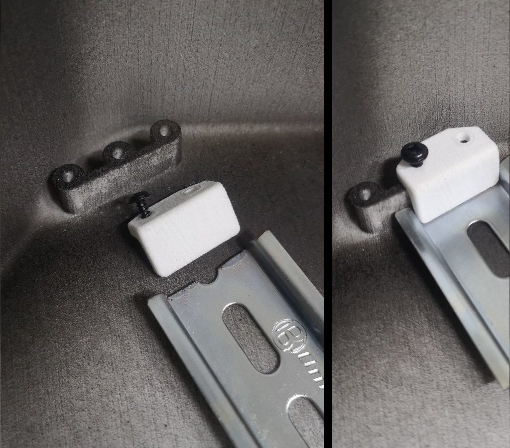
I also found a nice way to attach the DIN rail to the bottom of the box without increasing its thickness and consequently the whole box size, by using L shaped blocks screwed into raised towers to accomodate for the screw length. This way, no space is wasted and everything fits snugly.
At this point, we got confident enough to jump into the void and get a bank loan to go forward with the mold order. I can't even begin to describe the stress and fear that come from investing way more than you can afford on a single, vital part for your project that can make or break everything. I also have never been in debt in my whole life, so that's another worry I will have to carry for the next few years.
Well, here's the result: my business partner and me holding the first pieces out of the press, tired but happy like giving birth to a baby.
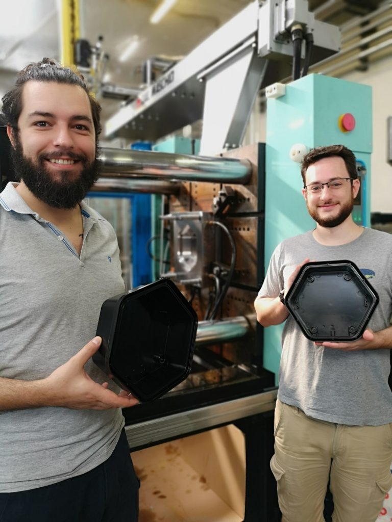
Isn't it beautiful? And it's all ours!
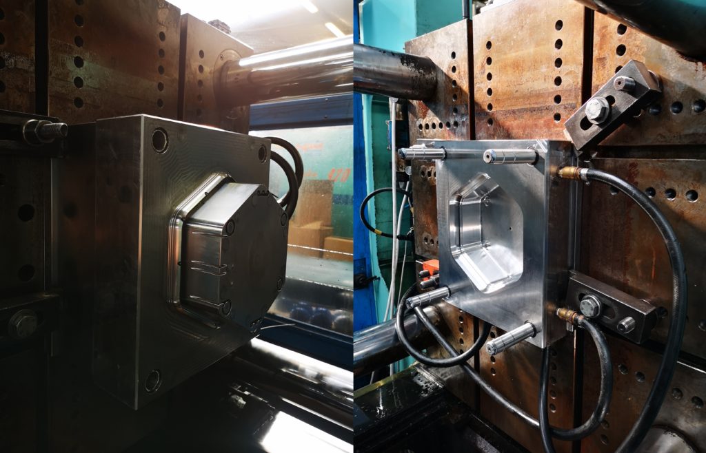
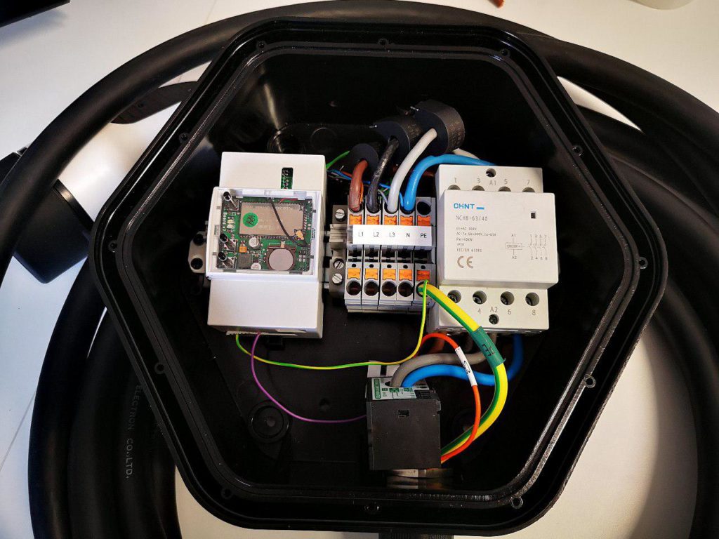
We ran home to test it, and here it is, with all the electronics assembled!
And everything was fine for a while, until we got the latest version of the EV cable samples from the manufacturer. They were 1mm wider than the cables we tested, and didn't fit the spiral cable fittings we used until now! This forced us to look for different holders, but the sizes are standard among manufacturers and most of them stop at 18mm diameter, with M25 threading. The few manufacturers making bigger ones have a M32 threading, that would still barely fit between the plastic reinforcement but only without the plastic nut:
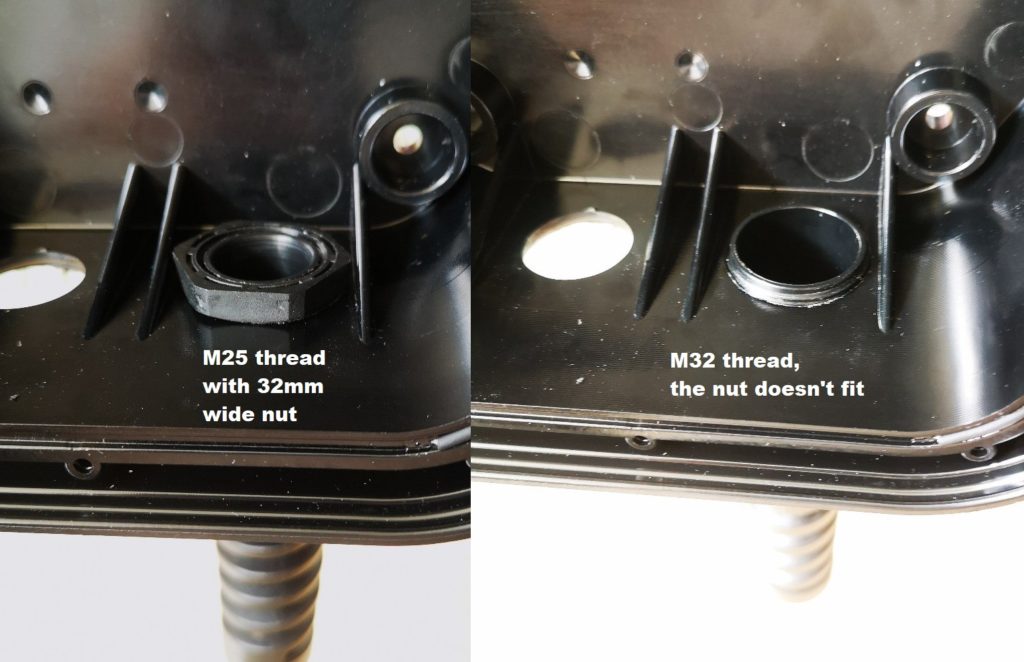
This got me quite worried, as we couldn't modify the molds anymore (well, you can but only by adding plastic, you can't remove existing features). I started thinking about every possible solution, from rotating the box 180° and place the cable on the other side (the plastic reinforcement weren't really needed from our calculations), to milling the existing glands and hope they don't break, to threading the plastic enclosure, maybe increasing its thickness. Then I started reading the fitting manufacturer's manual and found out that they also offer metal nuts, and they have thinner walls than the plastic ones that were delivered with my samples. Measures looked good, so I ordered some, and problem solved!
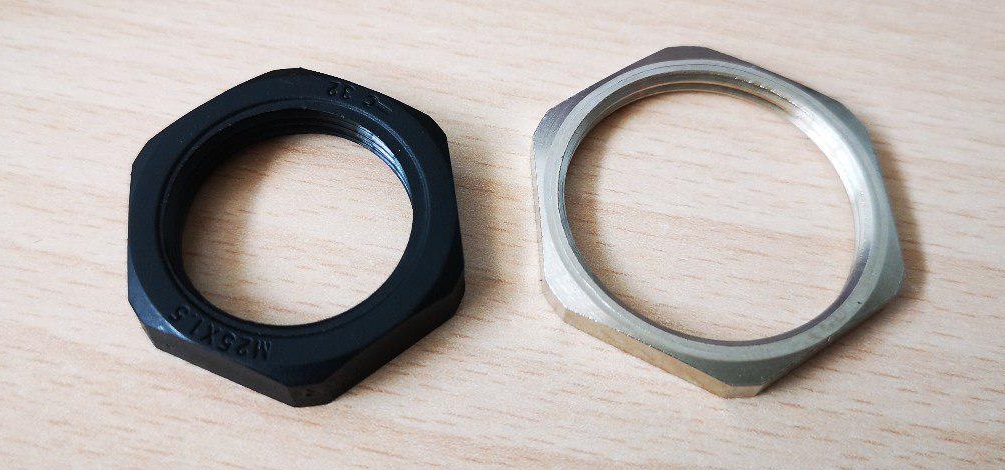
It fits!!
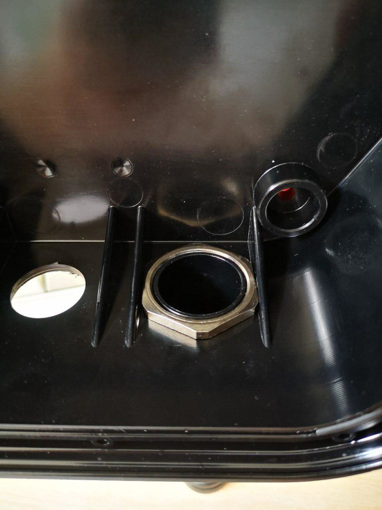
The problem here is that the nut fits too snugly, so I will have to improve my drilling fixture to account for this. We were quite lucky we didn't invest in a special mold with moving parts just to have that hole pre-made, as that problem could have been much bigger.
And here we are, to the present day. You may have noticed I didn't write anything about the cover in this log; that's a surprise that deserves a post of its own.
In the meantime, you can download the CAD files here.
 Mastro Gippo
Discussions
Become a Hackaday.io Member
Create an account to leave a comment. Already have an account? Log In.
Wow! That's awesome. I'm venturing into the EV arena, specifically with a focus on EV infrastructure and of course, along with it is the home charging requirements. You are absolutely spot on with respect to the adaptable charging rate requirement to address other loads and time of use issues. Actually right now I have a Tesla Wall Connector which I'm 'talking' to (see TWCManager) on github. I will integrate that with the OpenEVSE (I have two of those).
Your battle with enclosure design and manufacture is a necessary battle in the end to get a product that looks attractive yet robust. I come from a die-casting background so I understand the costs of tool design, and then the added options of including other feature. Meanwhile a tool design that doesn't require a lot of post op finishing after casting!
The other challenges we face are cables and connectors and then we have to get CE or UL approval - That can be expensive too. At least with CE it may be simpler if all the components meet CE requirements. Not sure how that works for enclosures though?
I'll be sure to keep watching!
Are you sure? yes | no
I think it's better to do it from the fiberglass, because of simple form. It's much less expensive and very convenient for low mass production. And the technology is simple. Look, here the horn from the fiberglass w/o any painting(pic from my friend, size around 31" x 23"):
https://sun9-21.userapi.com/c638917/v638917200/4f7c9/VKF6_MP2mXA.jVacuum plastic forming also a good way.
Are you sure? yes | no
We considered both solutions, but they wouldn't be practical for our specific design!
Are you sure? yes | no
Wow! This is a great read, thanks so much for posting. I'm sorry I didn't see this before meeting you at Camp last weekend or I'd have chewed your ear off about it for an hour or two :-D
Are you sure? yes | no
Haha thanks Mike :) I'm sure there will be other opportunities to meet and talk, maybe in Belgrade!
Are you sure? yes | no