This post is written by my friend (and now colleague/intern :) ) Michele.
Our target users for Prism are mostly hackers and passionate people playing around with EV technology; for this reason we strive to make Prism as safe as possible even for the most edge cases.
An essential part of the safety system is the RCM, acronym for Residual Current Monitor. As the name suggests, this component has one simple job: measuring current leaks. And I'm sure everybody here already knows how an AC RCD/GFCI works, or you can find plenty of great articles to learn from. To sum it up, the RCM measures the current passing through the neutral and live wires inside it. In normal conditions, all the current passing through the live wire should return back via the neutral wire, "cancelling" each other. In case of irregular operation - like someone touching an exposed wire - we have some current flowing to earth and not returning through the neutral. In this case the RCD detects this difference and signal fault on its output, triggering a circuit breaker to stop this current path.
And this is pretty easy if you're just measuring AC currents - a simple current transformer can do the trick. But our electric cars also contain high voltage batteries, that can leak dangerous DC currents! This risk is considered by standards organizations, and IEC released the IEC 62752 and IEC 62955 standards to describe the requirements for "In-cable control and protection device for mode 2 charging of electric road vehicles" and "Residual direct current detecting device (RDC-DD) to be used for mode 3 charging of electric vehicles". A DC RCM is not required for domestic installations, but since our customers will probably charge DIY EV conversions with increased risks of DC leakage we decided to include this protection by default.
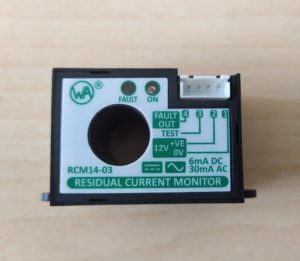
To comply with the standard we selected the RCM14 from Western Automation, a really nice and compact RCM that trips at 30mA AC or 6mA DC.
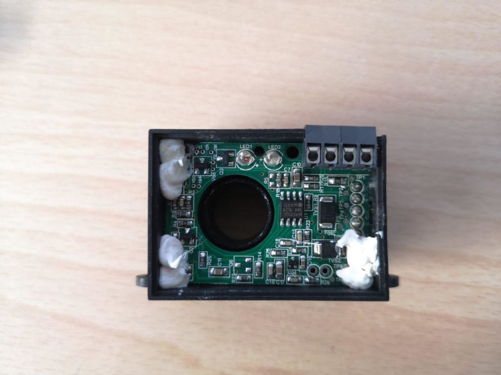
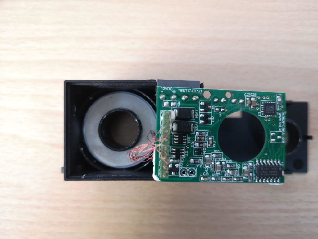
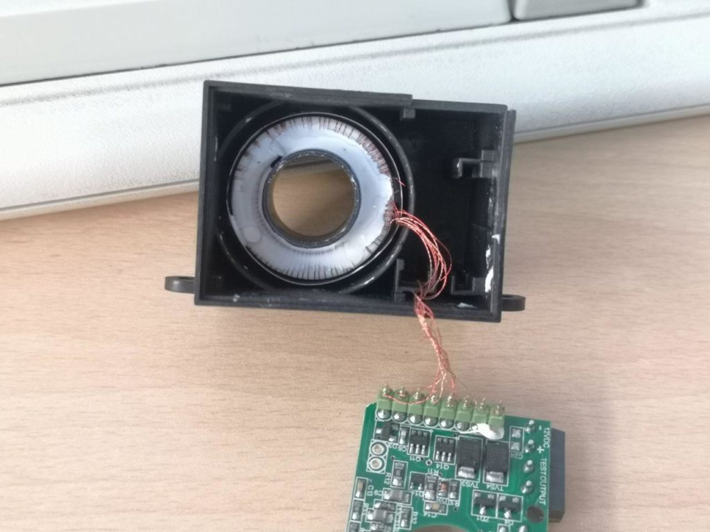
But how is it capable of detecting a direct current if it looks like a normal current transformer? Our guess was that they're using a hall sensor to measure that, but there's no trace of it inside:
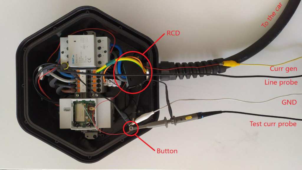
At that time Mastro Gippo was doing some performance testing on the RCM and the contactors. In his setup he ran a wire through the RCM, shorting a constant current generator through a switch. To measure intervention time, he connected one probe of the scope across the wire and the other probe to the contactor output.
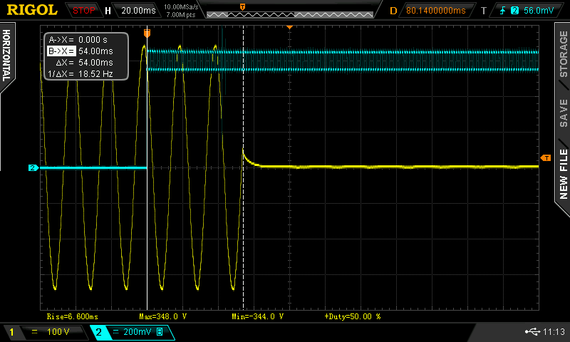
 This test showed interesting results: the current through the wire (in blue) was not constant, it had a square wave component!
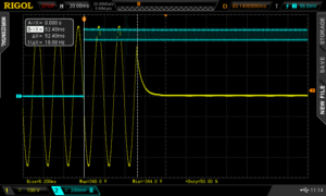
This gave us a precious hint to understand how this works.
The Fluxgate technology
The principle behind this application is the fluxgate magnetometer, a device invented in the 1936 and used during WWII to detect submarines.
Here is a simple explanation on how it works:
Fancy, isn't it? But I want to know more about how this device works, so let's dig deeper.
This type of magnetometer takes advantage of a property called magnetic hysteresis. If we apply an alternating magnetic field to a ferromagnet and plot the resulting magnetic field and the magnetic flux on a graph, we get something like this:
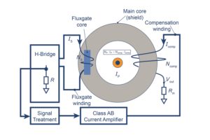
To measure this property we can take a ferromagnet, wrap two coils of conductive wire on it and apply a square wave to the primary coil (fluxgate winding in the picture below). The result is an alternating magnetic field or, from the secondary coil perspective (compensation winding in the picture), a square wave current. The hysteresis cycle is perfectly symmetric, so the resulting voltage is symmetric too.
This changes if there is a constant magnetic field B0 close to our setup. The cycle is the same, but instead of starting from the middle of the graph (B = 0) we start from B = B0. It's like having the same graph translated down by B0.
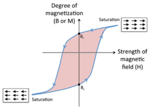
The cycle and therefore the voltage at the secondary is not symmetric anymore. We can measure this asymmetry and apply some math to get the value of the external magnetic field B0. This process is not simple, but you can learn some more details from this article. It involves harmonics and Fourier Series expansion!
 Fluxgate drive waveform (a), and Fluxgate current in the absence (b) and presence (c) of an external magnetic field
That's it: a DC current across the wire through the RCM will distort the symmetry of the fluxgate circuit which will fire the RCM output if this current is high enough.
So why was the current measured by Mastro Gippo a square wave instead of constant? The overlapping wave is caused by the magnetic field induced in the magnetic core by the fluxgate primary coil. The alternating magnetic field causes an EMF - and thus a current - across our test wire.
Mystery solved!
But what about the tests? Well, the standards define precise intervention time requirements:
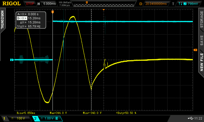
First we measure the net intervention time of the base circuit, from the moment the RCM signals a fault to the moment the contacts disconnect. All tests are performed in normal usage conditions, while charging a car; that's why the output voltage doesn't settle immediately (there are standards specifying exactly how quickly the voltage has to settle below a safe voltage, but that's the cars responsibility).
Worst case measured: 15,2ms.
Now we can add the RCM to the equation and measure intervention times according to the table (notice how the square wave becomes less influential as the current directly applied to the wire increases):
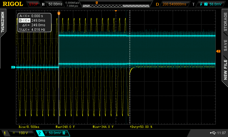
Test1 – 6mA DC
Required intervention time: 10s
Worst case measured: 249ms
Test2 – 60mA DC
Required intervention time: 300ms
Worst case measured: 54ms
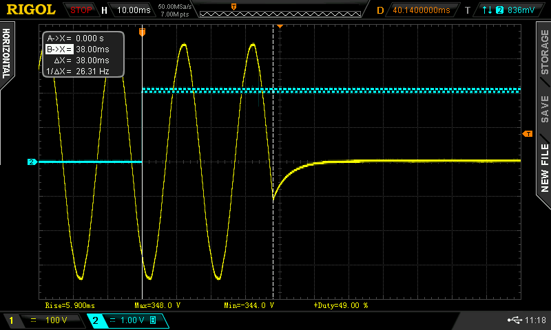
 Test3 – 200mA DC
Required intervention time: 100ms
Worst case measured: 38ms
All tests passed with flying colors! Stay safe :)
 Mastro Gippo

Discussions
Become a Hackaday.io Member
Create an account to leave a comment. Already have an account? Log In.