As I wanted to make my project better and fully comparable to original Odroid Go (OG) a made few more iterations. Because they are not so different from each other, I decide to cover them in one log and describe just changes which differentiate these versions from each other. .
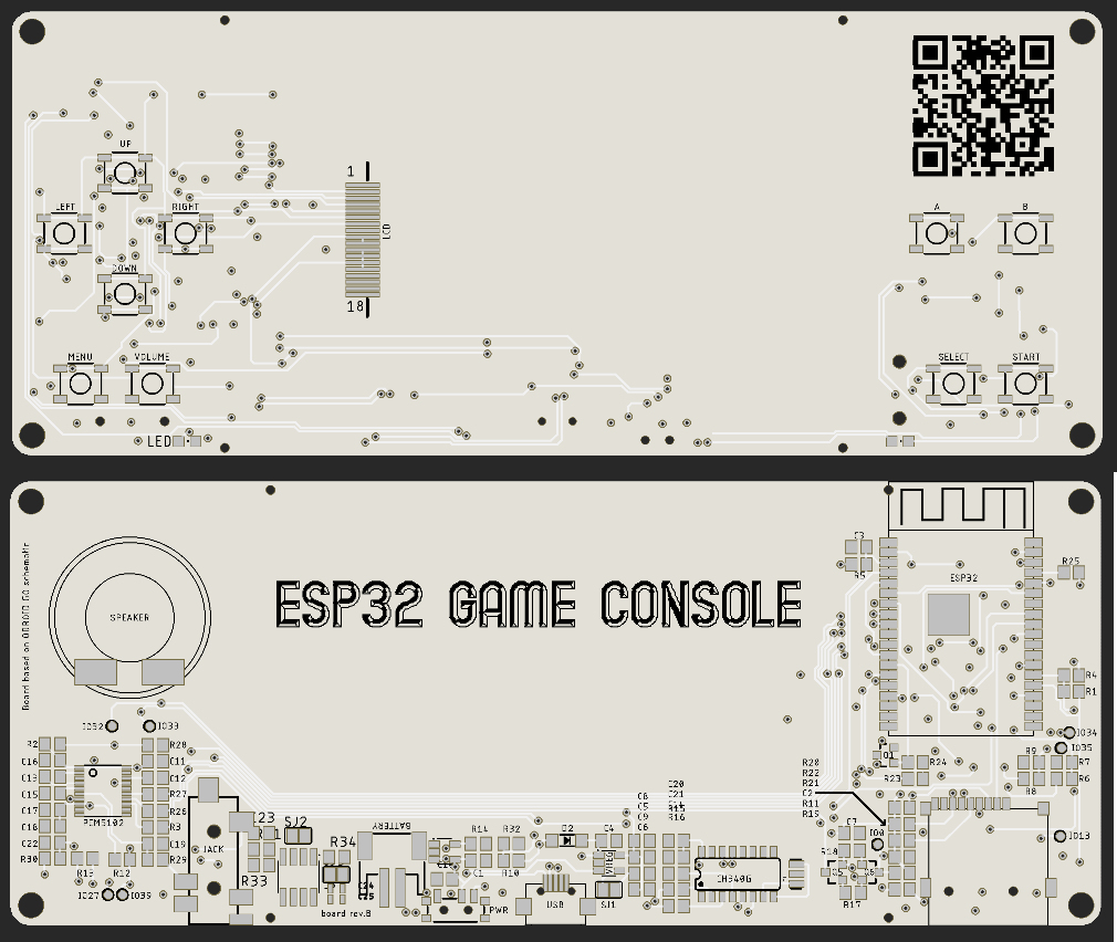
rev.A -> rev.B :
This version actually did not make it to the fabrication stage.
it contained:
- UART line repair from rev.A
- SMD 12 MHz crystal instead of that THT one
- different sound chip than OG has (LM4890) , but should play sound in all games.
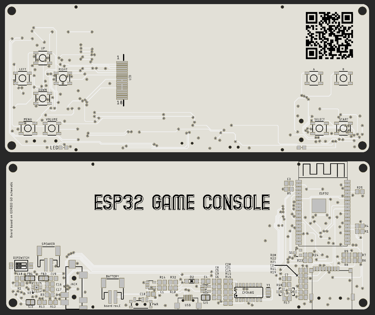
rev.B -> rev.C :
This version had different I2S sound chip ( I use MAX98357A). I also changed speaker connection from solder pads to JST connector and I added, but actually never used, DIP switches to change output volume of the I2S chip.
rev.C -> rev.D :
This is first version at which I used conductive buttons. If anyone will search for some library which can be used, I recommend library (for Autodesk Eagle) from 32teeth (Conductive buttons) . These buttons are used for D-pad and A & B. All other buttons are still micros switches.
Board is bit wider, because I could not fit these conductive buttons on the side of the LCD. I also moved all other buttons to top side of the PCB and arrange them vertically on both sides of the LCD, where they are not in way when someone is playing.
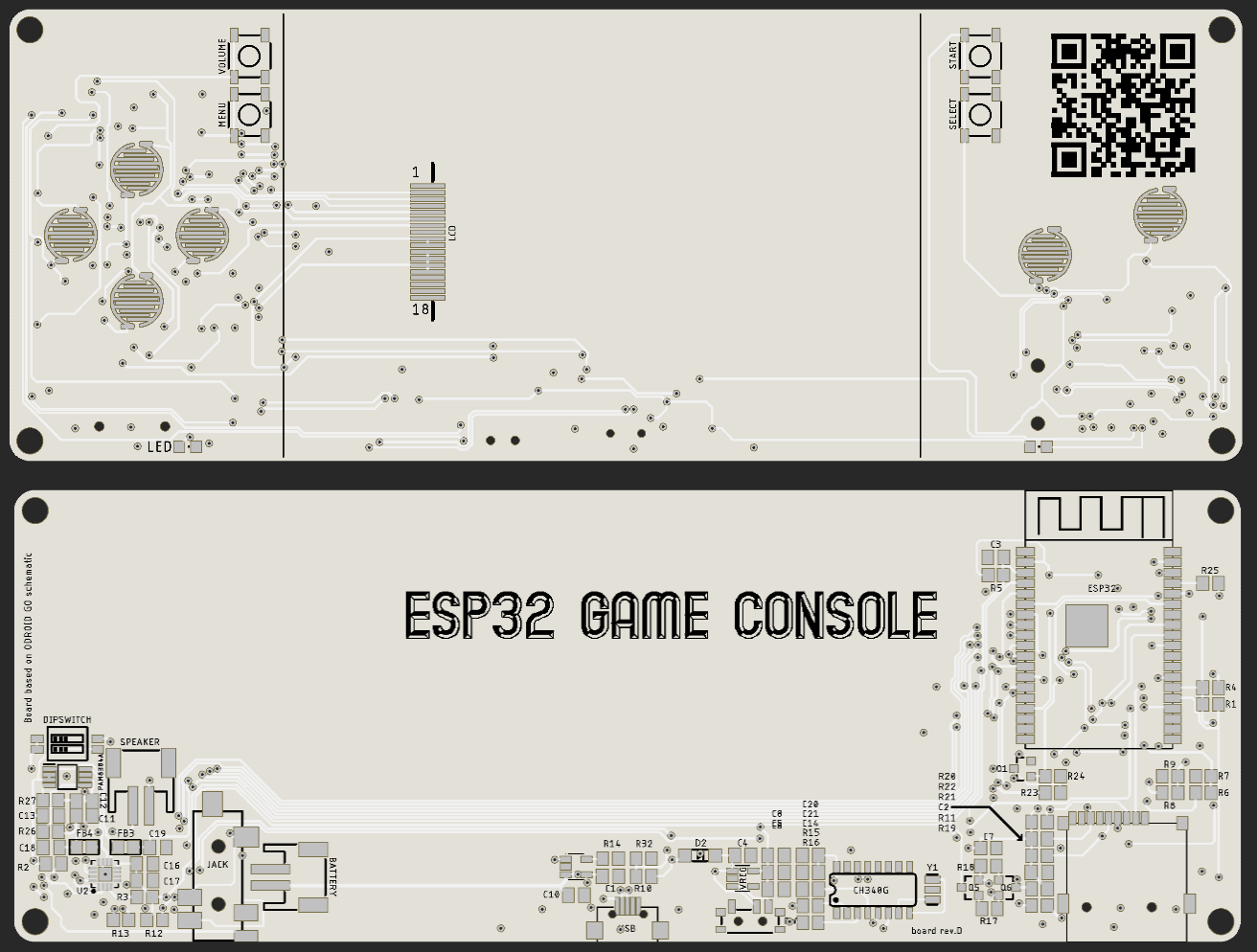
In this revision i used original sound chip from OG and same I2S chip as in rev.C . I also changed position of JST connector for battery, I moved it near to the audio jack connector at left side.
To make it work, I ordered rubber buttons from China for Gameboy. Because is quite hard to find some dimension for Gameboy (GB), I had to order spare case as well and when this arrive, I took measurements and put them in my design for 3D printer.
I assembled one of the boards and everything worked, but I had some problems with buttons. They fully worked if I pressed Right and Down button, but if I pressed Left and Up, they worked just sometimes. I was thinking that problem could be with different accuracy of the resistors (from original OG design) but I looked what accuracy I used and those resistors were 1% accuracy, so this could not be the case. I made few iterations of the 3D printed case and with one iteration, buttons worked almost perfectly so I toughed that this was just issue with placement of the rubber pads to the PCB. To support best alignment of the rubber buttons and PCB I looked at case for GB and add holes which are at original PCB of GB as well. All these changes are reflected in revision E.
rev.D -> rev.E :
Because I was not completely sure that my problem with bad button presses was 100% related to the placement of the rubber buttons and PCB, I made 2 version of this revision. First, which had all conductive buttons of the same design and second, which had conductive buttons for D-pad same as original GB. I also made two other changes. Firstly I moved JST connector for battery back to the middle of the PCB, as cable from battery was not bend in right way, when battery was inserted. Second small change was cut out for power switch, as this was hard to operate, when case of the console was put together.
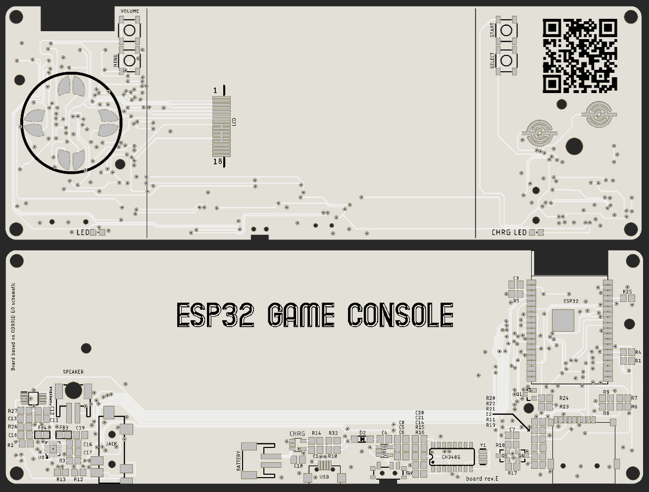
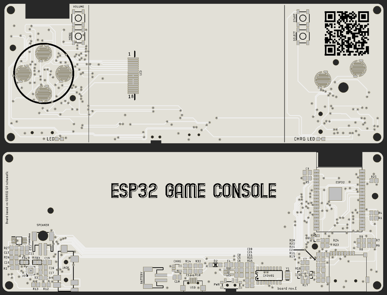
When I received boards, I assembled one and start testing. Alignment holes helped, but presses were still unreliable. Pressing Left/Up mostly worked but it was not consistent. To test, where are rubber buttons touching the PCB, I colored them with black marker, inserted them with PCB in the case and pressed them. This showed me that I have to move D-pad holder down about 0,5 - 1 mm, but after few iteration of the case, problem still appears. At this point I decide that I will not invest more time and money with this project and put all in the drawer.
 Miroslav Zuzelka
Discussions
Become a Hackaday.io Member
Create an account to leave a comment. Already have an account? Log In.