Summary
The various software tools were collected and deployed into a build virtual machine. A simple build was performed as a sanity check of the tools.
Deets
I generally use virtual machines for my project build systems. This make it easy to move around and archive, and to have a project-focused build machine. It also insulates me a bit from catastrophic systems failures that seem to happen every few years or so, because I can simply copy the virtual machine to the new system and carry on, instead of having to go through the Hell of installing stuff.
That being said, I am using a Windows virtual machine with VMWare Workstation. I haven't ever tried deploying these tools to a Linux system. It used to be the case that the chip manufacturers' development tools were rarely available on Linux, and you really had to be dedicated to get stuff working there, and so I have just always stuck with Windows in the interest of working on the project at hand rather that working on building ARM toolchains, trying to get device drivers to work, and trying to runs other Windows-only tools from the manufacturer. So Windows isn't free. And neither is VMWare. But it's a new era, and I think the STM tools might work on Linux. Similarly, you probably can get Oracle Virtual Box to work, too, if you want to have a build VM as I do. But you're on your own in figuring out how to do that. My only advice with Oracle Virtual Box is that I think you have to download and install an 'add-on' that give you the USB support. You will need the USB support to connect to the device programmer (and the USB of the BluePill if you want that, too).
The ST Microelectronics web site has all those tools for free download ('free' for the cost of registering yet another 'account' in some vendor's system). You will need:
- STM32CubeMX
This is a project configurator tool. You select your chip, configure the pins for the functions that you want, and it will emit a project replete with all the peripheral config code set up and the required peripheral libraries copied into project directory. Perhaps the most important part is the clock configuration. That chore is manageable on a simple chip like the the STM32F103 on the Blue Pill, but it's byzantine on a more complicated one like the 'F476. This tool also provides a few 3rd Party things, like FreeRTOS. - System Workbench for STM32
This is an Eclipse-based IDE. Yes, Java, my least favorite thing in the world. A third party ('AC6') packaged up the Eclipse with the gcc tools for ARM and OpenOCD for the programmer/debugger interface. I find that packaging very convenient, so I hold my nose with the Java and its glacial performance and Eclipse's glitchiness. - STM32 ST-Link Utility
This is not strictly required, but I find it convenient from time-to-time to do things like erase a chip, or dump it's contents. In particular, many of the Blue Pills come with a bootloader for Arduino stuff pre-loaded. The System Workbench doesn't know what to do about that. It's easiest to erase the chip with the ST-Link Utility separately once beforehand. Also, it is handy for proving that you have you ST-Link working with your board correctly separately of all the other myriad tools. If you cannot connect to your board with ST-Link Utility, the other stuff is not going to work, either. - STM CDC Drivers
If you're using an older Windows (as I am) you will need the CDC drivers. You won't need them straight-away, but later when a serial console is added over the USB port, these will be needed. If you're on Windows 10, you don't need to do this step because the stock driver will work.
Toys have arrived:
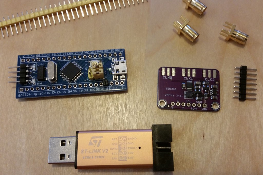
The blue board is the 'Blue Pill': the STM32F103C8T6 board ('Minimum System Development Board' as eBay vendors often call it). It's scarcely more than a breakout board itself. The violet board is Si5351A breakout board; it comes with some SMA connectors for the clock outputs if you want them (the clocks are also on the pin header). The golden dongle is a Chinese clone of the ST-Link v2 (and not a 2.1, this can matter when setting up with external tools, but this distinction doesn't matter here). It is not as full-featured as the actual ST-Link from STMicroelectronics -- it is only oriented towards SWD development (i.e. no JTAG), but that is fine and mostly a convenience, anyway.
Time to play...
Phase I -- Proving Connectivity with the Board
The first thing is to prove the ST-Link and Blue Pill are working together. This requires wiring some of the pins of the ST-Link to the pins on the end of the Blue Pill. It's useful to note that the debugging interface is SWD (an STM thing; similar in function to JTAG, but not JTAG), and moreover it does not bring out NRST. This has consequences later. (Strictly, NRST is brought out on one of the header pins, and you can use it if you want, but you don't have to do that if you make a configuration change in the IDE that I will describe later.)
The pins on the Blue Pill are Gnd, SWCK, SWDIO, and 3.3V. These need to be wired to matching pins on the ST-Link. If you're using the cheap Chinese clone, the pinout is printed on the device.
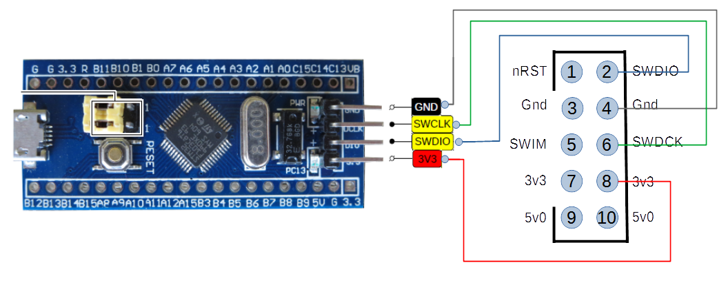
One thing to keep in mind is that even though there is a 3.3v connection over this set of pins, this is not for powering the board. Rather, it is so the ST-Link can monitor the Vcc of the board. You need to power the board separately, and that typically means plugging a USB into the Blue Pill and putting the other end... somewhere. It can be a port on your computer, or one of those cell phone chargers. Later, it is useful for it to be the computer, because we'll set up some USB functionality on it, but for now we just need it for power.
If you are using a virtual machine (as I am), you will possibly have to explicitly 'connect' the USB device to the virtual machine to make it available to the software running therein. The name of the device is 'STMicroelectronics STM32 STLink'.
Some Blue Pill boards come with a bootloader application that is handy for Arduino, but is problemattic for us. If the Blue Pill enumerates when you plug the USB in, chances are that it has the bootloader on it. If you use 'device manager' and see something like "Maple 003", then that is the boot loader.
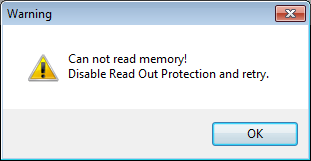
When you have this bootloader, the ST-Link will not be able to erase the device. Attempting to do so will result in this message:
What must first be done is to erase the readout protection bit (which will also cause the entire flash to be erased). This is done via 'Target', 'Option Bytes...', which will probably initially look like this:
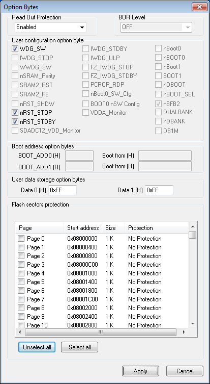
You will need to change the 'Read Out Protection' to 'Disabled'.
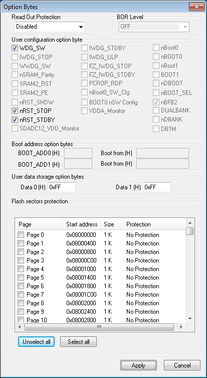
Then you can 'Apply', which will remove that protection (and also erase the device). Now you have revirginated your Blue Pill, and it should be usable with the System Workbench for STM32 (i.e. Eclipse). You probably will not need ST-Link Utility anymore, but I keep it around.
Phase II -- Creating a Project
As mentioned, I use the STM32CubeMX to create my initial projects (and later tweak them, as invariably you will). The gist of this activity is configuring all the peripherals, pin assignments, clock sources, etc., for the chosen chip. For complicated development boards with a lot of external peripherals, this can be a little chore, so I keep baseline CubeMX project definitions on-hand for reuse. I just copy and rename the file (the extension for the CubeMX definition is '.ioc') as appropriate for the new project. The Blue Pill is a simple board, so it's not too much work to create one from scratch, but it's still handy to have the baseline one to start with.
The CubeMX is a Java application, so expect slowness. Starting it up will put you in a kind of 'wizard mode' where you step through teh selection process. We would be using the 'MCU Selector' and it is easiest to just type in the part name 'STM32F103C8', and then choose 'Start Project' to begin configuration. This will land you on a view of the chip with the various leads.
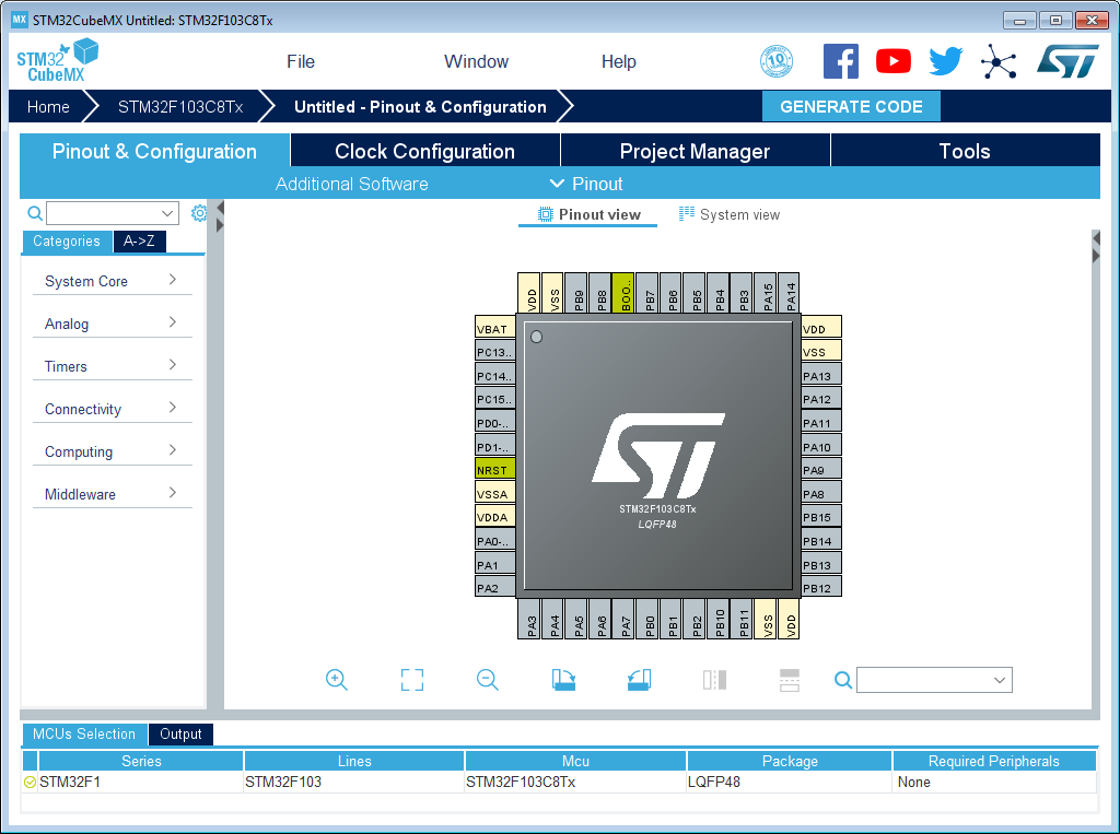
There is a separate page for clocks, on the 'Clock Configuration' tab, which show the default (which is how the chip powers up, with some on-chip low-speed RC oscillators):
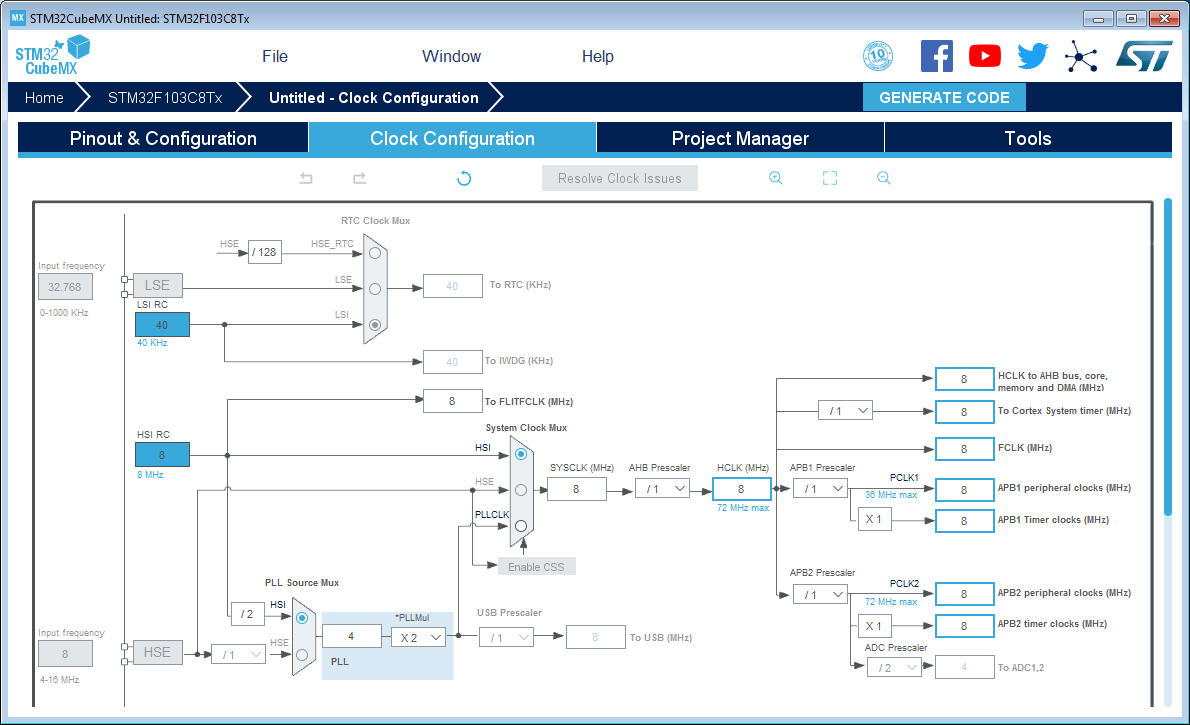
Note that you are not allowed to specify the external crystals at this point. To do that you need to fiddle with some other stuff first.
There is a separate page for saving the 'project', on the 'Project Manager' tab:
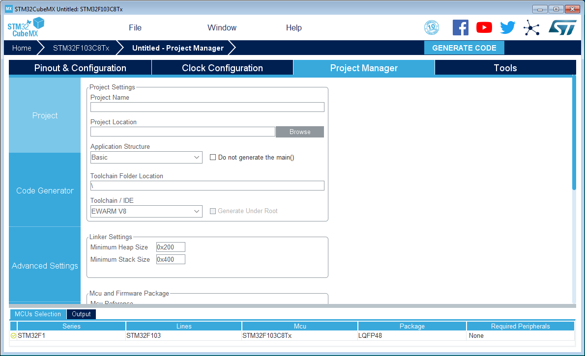
The 'Project Name' will become the filename that will be saved. The 'Project Location' will be where it will be saved, and that should be an empty directory at this point, because there will be a lot of stuff spewed into it later.
The most critical thing is the 'Toolchain/IDE', which should be set to 'SW4STM32', and 'generate under root' select. This will cause generated code to be suitable for the System Workbench for STM32 (i.e. Eclipse). I would go ahead and save that now.
One peripheral we will be wanting is the debugger port (SWD or JTAG, but we will be using SWD for the Blue Pill). That is under the 'Pins & Configuration' tab, and on the left under 'System Core', and there is 'SYS', and double-clicking that should make a config pane fly out, and on it there is 'Debug' which should be set to 'Serial Wire'. That will make the SWD port wired to the ST-Link active.
There is a 'Generate Code' button that you press to cause the project to be emitted. Go ahead and do that, and launch the IDE.
The first time you run System Workbench (i.e. Eclipse) it will want you to specify a 'workspace'. This is just a working directory where a bunch of temporary files per-project are kept. I keep a directory named 'workspace' and just let it always use that -- you can have a bunch of project that use the same workspace; stuff will be kept separate therein.
At this point there is a do-nothing application generated that will build and run. This is a useful time to get the ST-Link stuff setup so you can debug. There is a little trick to this with the Blue Pill because the NRST pin is not connected to the ST-Link, and the default is to expect that it is. However, there is nothing to edit yet because System Workbench has not generated any configs to edit yet. So, use the hammer button to 'build' first. This should build to completion because all this is wizard-generated code. After you have build, then we can start fixing things. First, there is a bug button that is used to start in the debugger, but don't press it. Rather, use the drop-down arrow next to it to present options. Here we want to choose 'Debug As' and 'Ac6 STM32 C/C++ Application'. /This/ will cause Eclipse to generate some stuff we will subsequently edit. What will actually happen, though, is that we will get an error message. It might be the cryptic 'failure in launch sequence', or maybe something slightly improved by now, but that's OK. What it will (or should, if we're on the same page) be failing for is simply that the chip can't be reset.
After that fails the first, we'll be in a position to fix it. Now under the same bug button dropdown, select 'Debug Configurations...' and you will be presented a dialog that has an entry for this project's debug configuration:
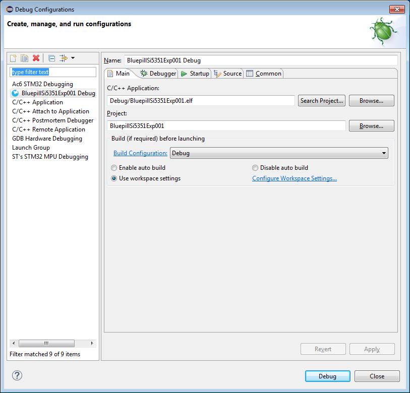
Critically, on the 'Debugger' tab is a button 'Show generator options...'. The settings we need are buried under there, so click it to expand stuff.
Under 'Mode Setup', the 'Reset Mode' must be changed to 'Software system reset'.
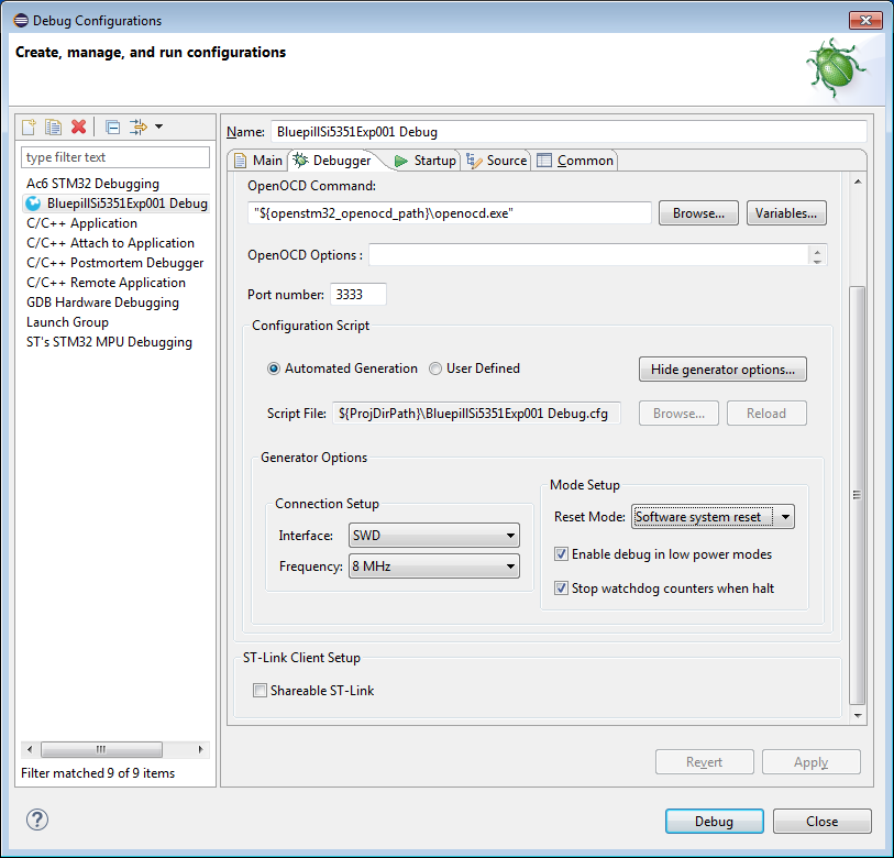
This means that the IDE will reset the chip via a SWD command rather than via twiddling the NRST line (which is not connected). This is the key. You can 'Apply' these changes, and close. Now if you click the bug button, it should connect successfully, erase the device, load the new firmware, and start running it. If you have not changed anything else, it should also immediately stop at the beginning of main(), so you can also single step. Single-stepping can be a very slow process over SWD and in Eclipse, so be patient.
Once this has been done successfully, you're off to the races. One last thing I recommend changing, though, is the fact that the IDE automatically creates a breakpoint at the start of main(). This annoys me, because I rarely want one there, and because breakpoints are a limited hardware resource and this uses one up. You can fix that in the same 'Debug Configurations...' dialog we just used.
On the 'Startup' tab, there is an option under 'Runtime Options' labeled 'Set Breakpoint at:' and an edit control with the text 'main' in it. This is what controls that automatically created breakpoint, and I deselect it. If I want a breakpoint at the start of main (I rarely do), I will explicitly set it myself.
With that sanity check out of the way, we can start to finish setting up the CubeMX project. Close System Workbench for now, and start CubeMX up (possibly by double-clicking the *.ioc file).
Phase III -- Finishing Up the Generic Project Definition
Earlier, we were not able to set the clocks for this board, because we hadn't configured the clock peripheral. On the 'Pinout & Configuration' tab, on the left, are some 'categories' of things we need to set up. In particular, under 'System Core' is 'RCC' which is the chips clock generation subsystem. If you double-click it, a pane will fly out with options. In particular, the 'High Speed Clock' (i.e. the 8 MHz crystal) and the 'Low Speed Clock' (i.e. the 32.768 KHz watch crystal) will be 'disabled'.
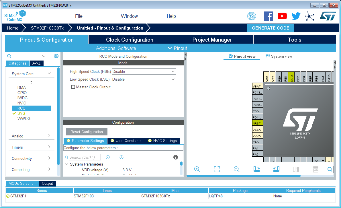
You'll want to set those to 'Crystal/Ceramic Resonator'. Doing so will now make it possible to make changes on the 'Clock Configuration' page! You can key in the frequency (8 MHz in this case), and select various multiplexer options to direct the clocks to the sources you want and fiddle with the speeds delivered to various subsystems. There is a 'Resolve Clock Issues' button that will help figure out what the prescalers and PLL values should be to achieve the speeds you select. Because I am running this project off external power, I set all those speeds to the maximum.
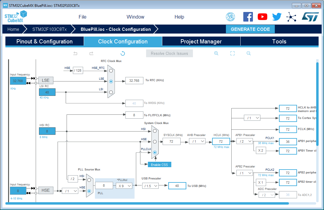
Then you'll go back to the 'Pinout & Configuration' and set up other stuff. For the 'baseline' project for the Blue Pill, I set the 'System Core', 'SYS' component to specify 'Debug' as 'Serial Wire', and also set 'Connectivity', 'USB' to select 'Device (FS)'.
Additionally, I configured a few pins: PA10, left click, select GPIO_Input (for now). Right click, select 'User Label' and change the name to 'BOOT_RX'. It is actually a UART that the on-chip bootloader (not the one we erased, this is from ST). I did similar for PA9, select GPIO_Output and naming it 'BOOT_TX'. I also changed PB2 to GPIO_input and named it 'BOOT1', and PC13 to GPIO_output named 'LED_D2'.
This should complete the things that are provided on the dev board. You might need to visit the Clock Configuration to make sure all the clocks are still OK after having fiddled with peripherals. You can then 'Generate Code' again. This will overwrite what was previously generated, and emit new setup for the peripherals that were added.
When re-generating code, the CubeMX avoids destroying your code if it is between protected regions demarcated by some special comments. The comments start like:
/* USER CODE BEGIN Includes */and end like
/* USER CODE END Includes */The specific name of the region will be different in different places. These comment blocks should not be altered or CubeMX will get very confused. Also, you cannot create your own 'USER CODE' blocks -- you have to use what CubeMX provides.
When I get all that stuff tweaked for the development board as it is out-of-box, I then archive the *.ioc for future projects with that board (you can discard all the other files -- they aren't archival). I do further tweaking on a project-by-project basis depending on the project's needs.
Phase IV -- Making the Project Specific Definition
Having made a copy for my new project, I then start tweaking stuff for the new peripherals I am goign to support. In this simple project, there's just a few:
- The UART1 will be used to receive data from the GPS.
- The I2C1 will be used to control the Si5351 chip.
- The USB will be set to the CDC profile.
- We will use FreeRTOS.
- Due to a quirk, we will set the system tick to be TIM2.
To start, I first setup the pins. Many of the peripherals have alternative pins that can be used for the same functions, so I find that specifying which pin before configuring the peripheral function results in less wasted effort than the reverse. The BOOT_RX (on PA10) needs to be changed to 'USART1_RX', and I change the label to 'GPS_RX'. The label makes it easier to read, but it also causes a #define to be emitted so it becomes a symbolic constant in your code. As such, the label names must be C language compatible identifiers. Similarly, I change PA9 to be 'USART1_TX' and labeled 'GPS_TX'.
PB9 becomes 'I2C1_SDA' and is labeled 'SI5351_SDA', and PB8 becomes 'I2C1_SCL' and is labeled 'SI5351_SCL'. That should be it for pin function specifications, now we have to tweak the peripheral settings.
Under the Categories 'Connectivity', the 'I2C1' configuration (double-click on 'I2C1' if needed to make the pane fly out), the I2C mode should be 'I2C' and below there is 'Configuration' with several tabs. In the 'Parameter Settings' tab there is 'Master Features', and 'I2C Mode' should be set to 'Fast Mode'. On the NVIC Settings I enabled both interrupt sources.
Similarly, under Categories 'Connectivity', the 'USART1' configuration, the Mode should be Asynchronous, Hardware Flow Control set to Disable, and the Parameter Settings Basic Parameters should specify 9600N81 since that is what the GPS module comes up as. On the NVIC Settings I enable the USART1 global interrupt.
Under the Categories 'Middleware' there is 'USB_DEVICE'. We can specify 'Communication Device Class' (under 'Mode').
Also under 'Middleware' is 'FREERTOS'. We should use Mode, Interface, CMSIS_V1 for compatibility with other generated code. There are a boatload of other options to tweak FreeRTOS's configuration -- you'll have to look at the documentation to see what all those do.
A quirk of running FreeRTOS on the CubeMX-generated project is the HAL libraries from STM want to use the SysTick timer for their own purposes. FreeRTOS by default wants to use it for the scheduler (that's what it intended for). CubeMX knows this and will issue a warning, but what you need to do is go to Categories, System Core, SYS, as set 'Timebase Source' to something /other/ than SysTick. I generally select 'TIM2'. This change will cause FreeRTOS to use Timer 2 for the scheduler instead, and the HAL libraries can then continue on in their assumption that SysTick is something they can use freely.
You might need to check the Clock Configuration to make sure that no issues arose, but they probably didn't.
Now you can Generate Code to make the boilerplate for the project. If you are creating this from scratch (i.e. you deleted all the prior stuff), you will need to go through the 'Debugger' setup steps again. Those choices are stored in the Eclipse project definition.
Next
Project Architecture
 ziggurat29
Discussions
Become a Hackaday.io Member
Create an account to leave a comment. Already have an account? Log In.