 ziggurat29
Summary
The high-level structure of the project is defined. It's fairly simple, and plenty of implementation can proceed in advance of receiving the GPS modules.
Deets
My plan is to use ye olde STM HAL and FreeRTOS for the base system. This is doable on the BluePill, and I've done so successfully with other projects, but it's not the most parsimonious approach with respect to systems resources (especially flash and ram). I'll have to keep an eye open for resource constraints as the project evolves. The BluePill has 'only' 64K flash and 20K RAM, which is tons if you're doing a cyclic executive (i.e. 'the big loop'), but that can get rapidly consumed by such abstractions as you use them more. Time will tell, and if I can get away with it, then I've saved a bunch of time.
My current working theory looks like this:
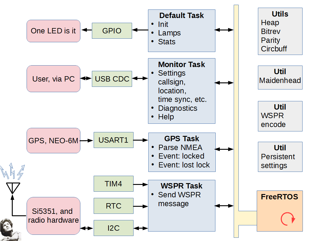
(yes, I am a horrible diagrammer)
Broadly, the project will be created as four FreeRTOS 'tasks':
- the Default task
CubeMX will create a 'default' task when generating code. Due to the peculiarities of CubeMX's code generation system, I find it less trouble to just use the default task for something rather than try to delete it (because the next time you run CubeMX, it will regenerate it, or at least become confused). In this case, I use it to initialize and wire together the various sytems components, and then run in a loop managing UI and periodically collecting memory statistics.
The UI in this project consists of one whole LED. The 'management' of that LED is that there is a convenience function that allows one to light the LED for a specified period of time, so this task handles the expiration of that time period and extinguishing of the lamp. Blink patterns could also be supported here, but I don't plan on using blink patterns in this project at this time.
The periodic collection of memory statistics consists of watching the maximum stack usage of each of the tasks, the maximum and minimum usage of transmit and receive buffers, the heap utilization, etc. These statistics are useful during development for tuning various memory allotments. At release time they are not particularly useful, since tuning should then be complete. - the Monitor task
This provides an interactive command line interface over an I/O stream. (I still call these things a 'monitor' just out of old habit. Maybe I should call it a CLI or something more '90s-era.) I generally make this facility operate over a stream abstraction of my own construction because then it is trivial to bind it to any serial port, network (or even SPI in a pinch I suppose). Here is it planned to be on the USB providing the CDC class.
There are a few persistent settings that need to be made, such as your call sign, and also I do want to support running the project without GPS. That will mean needing to set/sync the clock explicitly, and providing location (either lat/lon or maidenhead). Probably serial port parameters as well, in case for some reason one wants to use a different speed to the GPS. The one I have selected used 9600 bps as default out-of-box, but I know others use 4800.
'Help' is a baseline command.
Additional features useful during development are diagnostics, such as dumping the memory usage stats collected in the 'default' task, and also a generic hex dump of arbitrary memory locations. - the GPS task
This handles the incoming data from the GPS module, parsing the sentences, and acting upon the received data. In this project, we are specifically looking for lock/loss-of-lock events, the lat/long location, and the time. These are used to set some global quantities and stimulate notifications to other processes which will handle them in their own ways. (E.g., the WSPR task will need to know if it should be transmitting based upon there being sufficient information to do so, namely location is valid and clock is valid.) - the WSPR task
This is the value of the project. The WSPR task handles the scheduling of outgoing transmissions, and the shifting out of the bits into the direct-digital-synthesis module.
The implementation of the tasks are supported by a bunch of Utility modules. There are a bunch of utils I have created and re-use in various projects which provide things like an I/O stream abstraction, circular buffers, table-based computation of parity, bit reversals, etc. Additionally, for this project there are some new utilities such as converting a lat/long into a maidenhead grid locator value, and encoding a WSPR message into a buffer suitable for directly shifting out via modulator.
One other that I commonly use, but which is ultimately project-specific, is a 'persistent settings' feature. This simply stores a C-style struct into the last page of flash. And elementary form of wear-leveling is performed.
The tasks are expected to communicate with each other via Inter-Process Communications facilities provided by FreeRTOS. There are several to choose from, but I usually go for the 'task notification' feature. This is a FreeRTOS-specific concept, and essentially it is a bitfield that you can set and cause the task to wakeup and take action upon the change. I like this feature because it is lightweight on resources. But other mechanisms such as semaphores and message queues exist as well if you need them.
There are various on-chip peripherals that are used by the tasks. There is only one LED on this board, and I don't plan on adding any other physical UI. That LED is controlled via a GPIO pin, and is managed by the Default task.
The Monitor task presumes an I/O stream abstraction, and so is hardware-agnostic, but the init activities of the Default task will bind the Monitor to the USB CDC stream. Similarly, the GPS task will be bound to the UART1 stream.
The WSPR task interacts with several peripheral resources.
- The TIM4 will be used for generic one-shot precision timing. These timing events will be used to shift out the bits of the currently transmitted WSPR message to the modulator.
- The RTC will be used to generate an Alarm interrupt event. This event will be used to schedule the start of transmission.
- The I2C is the mechanism used to control the Si5351A clock chip that we are using as a DDS synthesizer.
There are just a couple pieces of external hardware:
- the on board LED. 'nuff said here.
- the ublox NEO-6M GPS module connected to the USART1 resource.
- the Si5351 breakout board connected to the I2C1 resource.
- the RF section. I plan for this section to be very simple. The goal of WSPR is to transmit Weak Signals (or 'QRP' in ham jargon), so I do not plan on providing a power amplifier. But we'll see. However, the Si5351S is really a clock signal generator more than a DDS, and it outputs square waves. There needs to be thorough filtering of the harmonics in order to be legal. I plan to use some sort of passive filer/matching network for this part. I haven't really figured it out yet, but for starters I will probably support one band -- probably 20m -- and have a single low-pass filter for such. After that works, then I'll think about how best I can support multiple bands. Everything in this project except for this final filtering stage is capable of multiple band operation.
Next
Implementing infrastructure and the Default task.
Discussions
Become a Hackaday.io Member
Create an account to leave a comment. Already have an account? Log In.