Summary
It turns out that I did not strictly need the power amplifier after all. Rather, I discovered that the synthesizer's frequency was off due to incorrect crystal loading, and other variances. I altered the loading and provided a correction feature. After getting the signal to be much more accurate, I am now able to transmit a weak signal that can be received by others without a power amplifier. But I'm still going to make the power amplifier, anyway.
Deets
I was making some minor enhancements and bugfixes and verifying that this didn't cause any regressions in functionality. That meant verifying that the modulation still worked, and I was doing that by receiving signal leakage with my HF radio and using the WSJT-X to decode it. However, for whatever reason I didn't really notice this on the WSJT waterfall display before, but my signal was off quite a bit; in fact it was off to where it was well outside the 200 Hz passband for the WSPR signals. So it had no business being decoded at all. But I also noticed multiple weaker images of my main signal periodically spaced. I had noticed before that sometimes I would get decoded twice, and suspected some sort of harmonics being involved, though I really only expected harmonics from the square wave output of the synthesizer, and those images would be far, far away from this band.
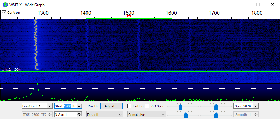
(Incidentally, the green line between 1400 and 1600 is the 200 Hz WSPR band, and the little red box under 1500 is the center sub-band -- numbered '16' in my scheme. Also, I find if you change the 'N Avg 1' to '1' from the default of '3', then you can make out the WSPR bits as the FSK.)
The WSJT-X waterfall display lacks many features -- I wish there was a 'cursor' feature that would at least tell you the frequency over which you hover, and preferably the magnitude of the signal, but I suppose this display is not meant to be taken too seriously and so there's not a ton of effort that goes into it's implementation. At any rate, guestimating the spacings from the display, it looked like 120 Hz. I.e., twice the mains frequency (here), or what you'd expect if the power were full wave rectified somehow. Fiddling with the 'band' feature, I was able to manually keep one or two of those harmonic images in the 200 Hz window, and was able to confirm that the presence of two harmonic images in the passband did cause two decodes, and when just one was there, then only one decode happened (my software by default hops around the passband randomly transmission-to-transmission). When I had two in the passband I was also able to confirm the 120 Hz spacing because WSJT-X reports the center frequency of the decoded signals. My guess is that some sort of power supply hum is coupled into the unit and is causing a mixer interaction with the synthesized signal, thereby causing these images. The project is quite a kludge in its present form!
<<XXX images -57 dbc image>>
The first concern was the fact that my intended signal was so far off from the mark. I vaguely remembered that there was a register for specifying the crystal loading capacitance, and confirmed that the software was not setting it at all. The default is 10 pF. Breakout boards such as these from China are typically short on specifications,, but I noticed the Ada Fruit boards mention setting it to 8 pF. I added some code for that, and my main signal moved, but now just above the passband; lol!
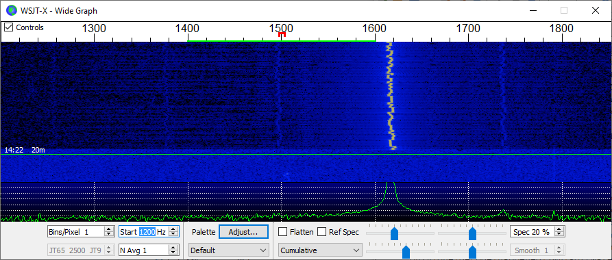
So maybe I need 8.75 pF? Well, that's not an option. I imagine there is perhaps still not a perfect loading of the crystal, and that there are perhaps some other basic variances. I added in some code to provide a compensation factor. It's just a constant parts-per-million value that is saved with the persistent settings and used when computing the values for the main PLL. I added a new persistent setting and some code in the command processor for it and fiddled with the values. I made this setting used every time a new tone is emitted, so changing it is interactive. This allows me to tweak the value until it winds up where I want it to be. For example, setting the 'band' to 16 (i.e. not random and explicitly at the center of the WSPR band), I was able to use the WSJT-X display to perform the tweaking:
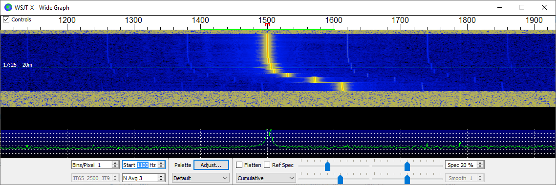
I then tested that all the bands 0 - 32 wound up where expected into the 200 Hz passband. In my case it was -273 ppm, which seems really quite high for a crystal, but whatever this is a breakout board. Fearful that my correction code would only make corrections for 14 MHz where I had developed/tested it, I tried it on 7 MHz and found that the compensation worked correctly there, too, so I feel pretty good about the computation.
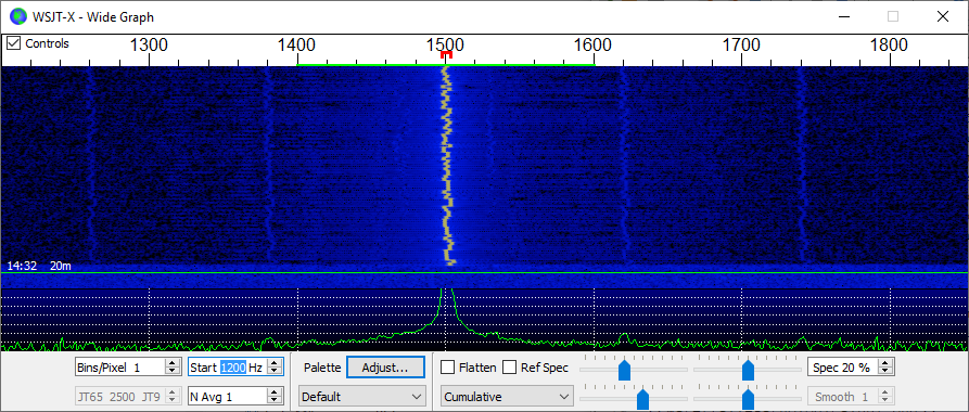
In addition to this tuning method, I also added a new feature to emit a 'reference' signal. You simply use the command 'ref ffff' and frequency ffff will be emitted CW. Don't use it with an antenna attached! But you can also use that with, say, a proper frequency counter, or perhaps by beating against WWV to figure out the proper compensation factor. Once it's set for your board, you can 'persist' the value and you should be able to just forget about it henceforth.
I wanted to try 40 m as well, but I had not created a filter for that band. Then I realized that since that band is harmonically related to the 20 m band, and because the spurs I am concerned with are the odd harmonics, that my existing low-pass filter will still work OK for the 40 m band. Changing the dial frequency to 7.0386 MHz and letting it continue to run for a little while shows spots there, too!
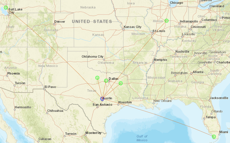
Well, now it proves that it can be used without a power amplifier at just 11 or so milliwatts (!), so maybe my antenna is not completely hopeless. But since I had already started thinking about a power amplifier I am going to plow forth with that plan, anyway.
Next
Back to the power amplifier...
 ziggurat29
Discussions
Become a Hackaday.io Member
Create an account to leave a comment. Already have an account? Log In.