In the last days I've finally decided to go to the "nearest" (about 15km far) electronics shop to get the missing components. While I've got almost all passives values wrong, they've not affected as much the results.
The good thing is that, after days spent thinking why the signal wasn't centered at my reference voltage, I realized I didn't AC coupled the in-amp: electrodes are adding some DC offset to the signal, and a high pass filter will not filter the whole DC out.
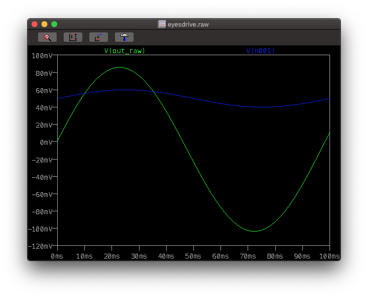
So I opened LTSpice and redesigned the preamp stage, here's the result (blue signal is the original one, with an offset of 50mA circa):

After redesigning the whole preamp stage, the signal is centered at around 2.5V, and now I only need to filter out the signal to complete the design.
I'm also considering to buy an oscilloscope, probably with it I would have seen the DC offset times ago with the FFT (the LabVIEW FFT is crap) and considered the AC coupling, but nowadays DSO are quite expensive.
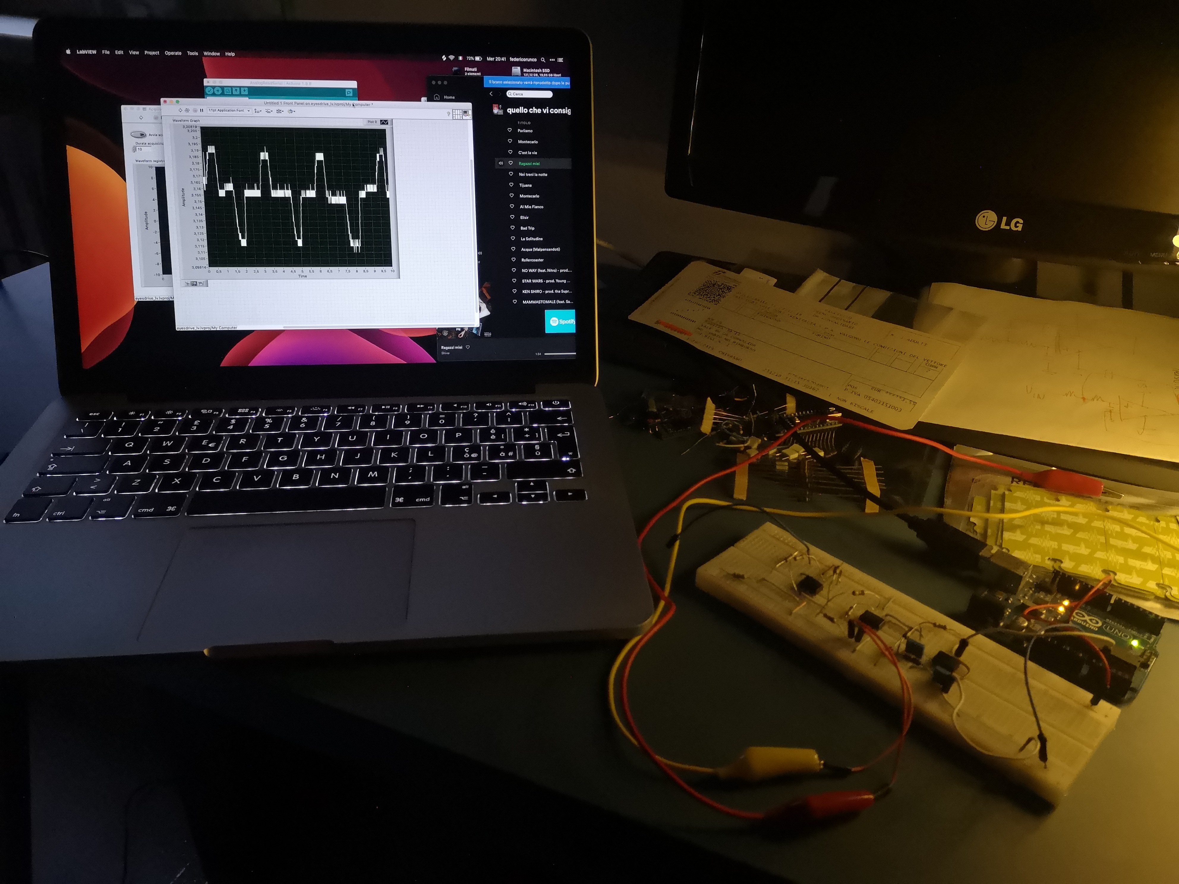
Here's a recording with the actual circuit, and yes, I'm using an Arduino as a myDAQ, also these things are quite expensive.
Only the preamp (that is the circuit on the breadboard) uses 3 op-amps without filtering. I don't know how many IC will be used in the completed board.

 Federico Runco
Discussions
Become a Hackaday.io Member
Create an account to leave a comment. Already have an account? Log In.