John Lonergan
-
Coming together
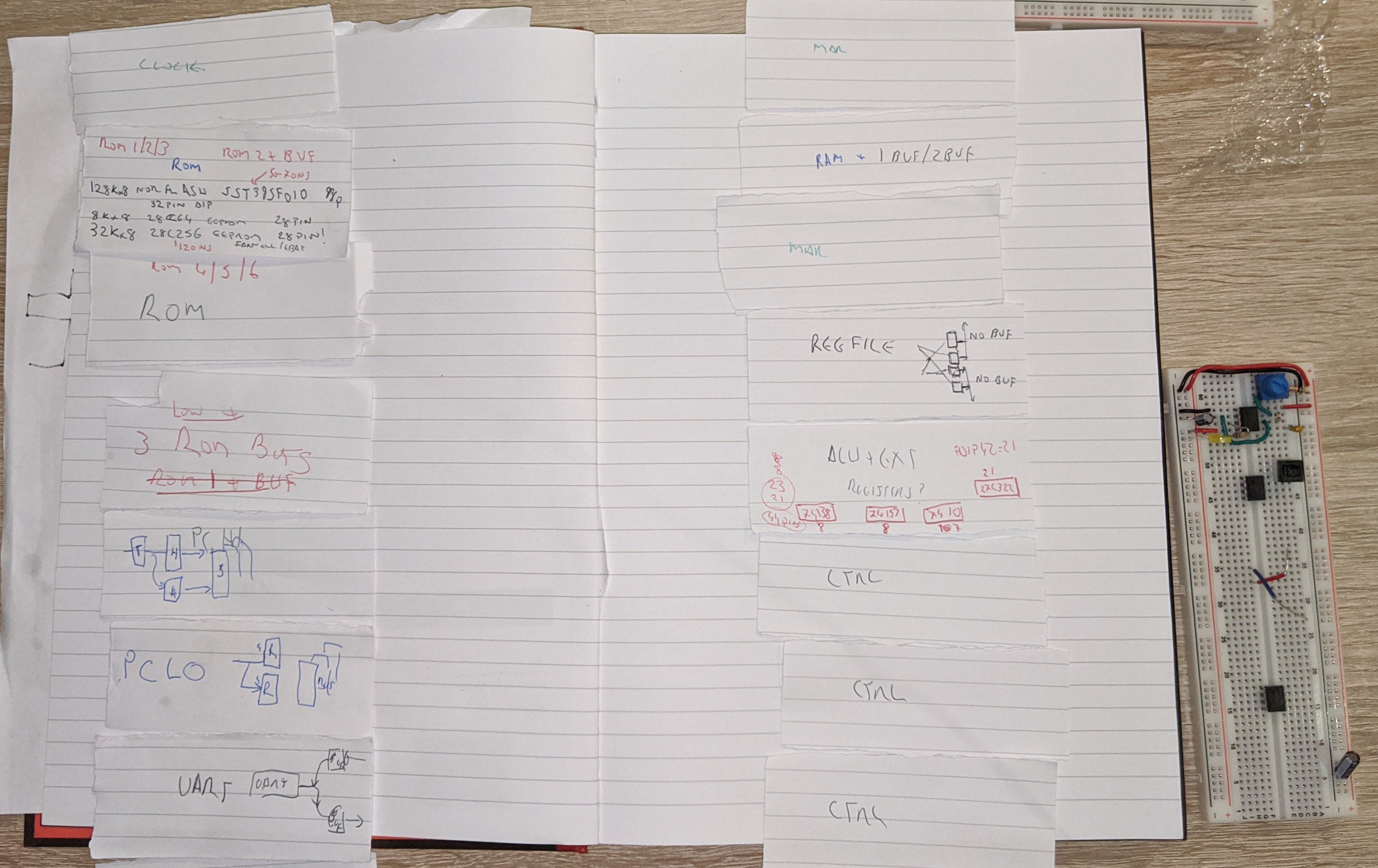
01/31/2021 at 21:14 • 0 commentsProgram ROM and control logic module needs building as you can see in the photo below.
The "ROMs" I am using are flash devices SST39SF010 128KByte and I'll only use 64K. Detailed board layout to follow. May lead to moving the clock module to the right hand column. We'll see.
I also want to find space for an indicator block with 7 seg displays showing the 3 ALU busses at least and possibly PC address as digits. I have an idea to build some 8 bit parallel to dual 7 seg modules.
![]()
Original paper layout...
![]()
-
UM245R - How to use video
01/25/2021 at 02:48 • 0 commentsCovers same content as previous log.
-
UM245R - USB to 8 Bit Parallel Transceiver - How to use
01/24/2021 at 18:21 • 0 commentsAs one of the modules of my "TTL" CPU caled SPAM-1 I’ve been wiing up the UM245R serial to parallel UART from Future Tech Devices Inc FTDI.
See datasheet :https://www.ftdichip.com/Support/Documents/DataSheets/Modules/DS_UM245R.pdf
I’m using it to provide a convenient way to allow SPAM-1 to communicate with the outside world.
For simulations of my whole CPU I’ve also written a complete Verilog model of the UM245R UART to send data to a graphics terminal I’ve written that runs on my PC and which I will also be able to hook up to the real UM245R once the project is built. https://github.com/Johnlon/spam-1/blob/master/verilog/uart/um245r.v. The verilog model allows remote control of the simulation.
So, I thought I’d share what I’ve learned and I’ll hopefully do a video about the Verilog simulation if I can figure out an approach that makes sense.
Anyway, the first and perhaps only big decision you have with this device is to decide how it will be powered.
Two options:
- Bus Powered where we power the UART and the surrounding project from the USB power
- Self Powered where the surrounding project supplies the power – eg from batteries or a PSU
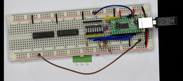
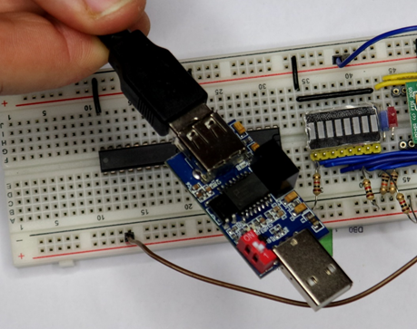
You can see the work-in-progress below in bus powered mode, with some LEDs on the data lines (ignore the two buffer chips which will provide connectivity to the rest of SPAM-1).
It is wired up in USB "bus powered" mode which is the default it will arrive in.
When you connect the UART to your PC then it will hopefully automatically install the Virtual Com Port (VCP) drivers.
The drivers can be found here https://ftdichip.com/drivers/vcp-drivers/
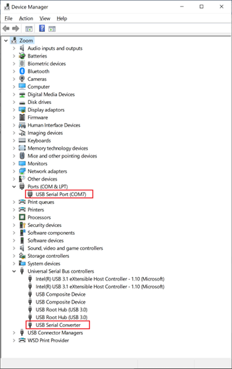
Once you plug in in then the device should appear in Device Manager. On my machine in the ports group and also the serial controllers group.
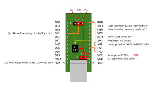
If you project will run off USB power then you are in luck as that is the default configuration of the device.
There are a couple of jumper on the board that provide power configuration. if you are going to connect using USB power then you leave these jumper here in the default position which is shown here. You can see here in the data sheet the circuit you'll need for USB power and basically, there is nothing to it.
Since you are powering this UART device from USB the assumption is that you will run your entire project from the USB power.
The UM245R has two signal lines that tell us whether the UART has received data from USB and needs to be read by the project, or whether the UART is ready for data to be written through it back to the PC or whatever its host is.
To communicate with the device you need to monitor the state of two signal lines:
- _RXF indicates whether the buffer in the FT245 chip has received USB data.
- _TXE indicates that the device is ready to accept a byte to send to USB.
Additonally there are RD and WR enable likes and the 8 data pins.
If I want to send data to the USB host (ie laptop) then I need to put some value on the 8 data lines and then bring the WR enable line low. Only do this when _TXE is low.
When _RXF is low then it’s ok to bring RD low to place a received byte on the 8 bit bus.
So, your project simply needs to monitor _TXE and _RXF to device when it’s time to receive or send data and then manipulate the RD/W# lines to execute the send / rcv.
But, I’m not interested in running off USB power for a few reasons…
- It’s inconvenient to have to power the modules via the UART USB during development
- I don’t want to have to connect it to my laptop at all to be honest unless I absolutely need to
- I may want to draw more current than I’d be happy to pull from the laptop – LEDS, EPROMS all add up.
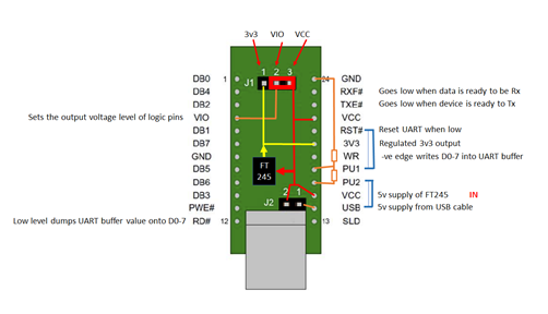
If your project isn't going to run off USB power then you will have your project powered by it's own supply - batteries or whatever
In SPAM-1, my TTL cpu project, I'm going to run it off a 5v breadboard power module connected to batteries.
In this case then we need to look at section 7.2 of the data sheet for the wiring diagram and notes to understand what’s needed.
We need to add a link as shown above from the UART’s RST# to PU1, and another link from PU2 to USB which is the 5v coming from the USB cable. The purpose of this wiring is to ensure that the device powers down when the USB cable isn’t connected. The device uses a few 10’s of uA when the UART is in its reset state, but it only uses 15mA when connected. In order to minimise power the circuit diagram is driving the RST# signal from the 5v on the cable in way that when the cable isn’t connected then RST# is held low, but pulled up to logic 1 when the cable is connected. PU1 and PU2 according to the diagram on page 24 are nothing but the terminals of a 50% voltage divider between whatever PU2 is connected to and Ground. So if PU2 as wired to the USB “VBUS” cable power line then when the cable is plugged in then PU1 and therefore #RST will be 2.5v which is logic high and this will take the UART device out of Reset. Alternatively, when the cable isn’t connected then PU1 and RST# will be logic 0 and the device will standby.
EPROM configuration
Section 7.2 also states that the on-board EPROM ought to be changed from the default of “BUS Powered” to “Self Powered”.
Unless you are planning on building a product then I believe this change is actually optional and solely about telling the host what to expect in terms of power demand. It is part of the USB spec to send a descriptor from the USB device to the USB host (the PC) to tell the host what the power demands are. The USB standard says you must do this but to be honest unless you are building a product for distribution then you can skip this step.
Hooking up a serial console
I found using the Arduino IDE’s serial console most convenient to start with, and that’s because that tool tells you which virtual com port is being used by the UART and automatically hooks the serial monitor up to it.
If you know the port then you could switch to putty or whatever tool you like.
But what baud should you use in the serial console?
Well, apparently it doesn’t matter.
https://www.mouser.com/datasheet/2/117/usb245r-ds-v10-14240.pdf says
"By using FTDI’s Virtual COM Port drivers, the peripheral looks like a standard COM port to the application software. Commands to set the baud rate are ignored; the device always transfers data at its fastest rate regardless of the application’s baud-rate setting."
So apparently it doesn’t matter what Baud rate you set the serial console to.
For bits/parity/stop I used “8-N-1”.
Verilog simulation
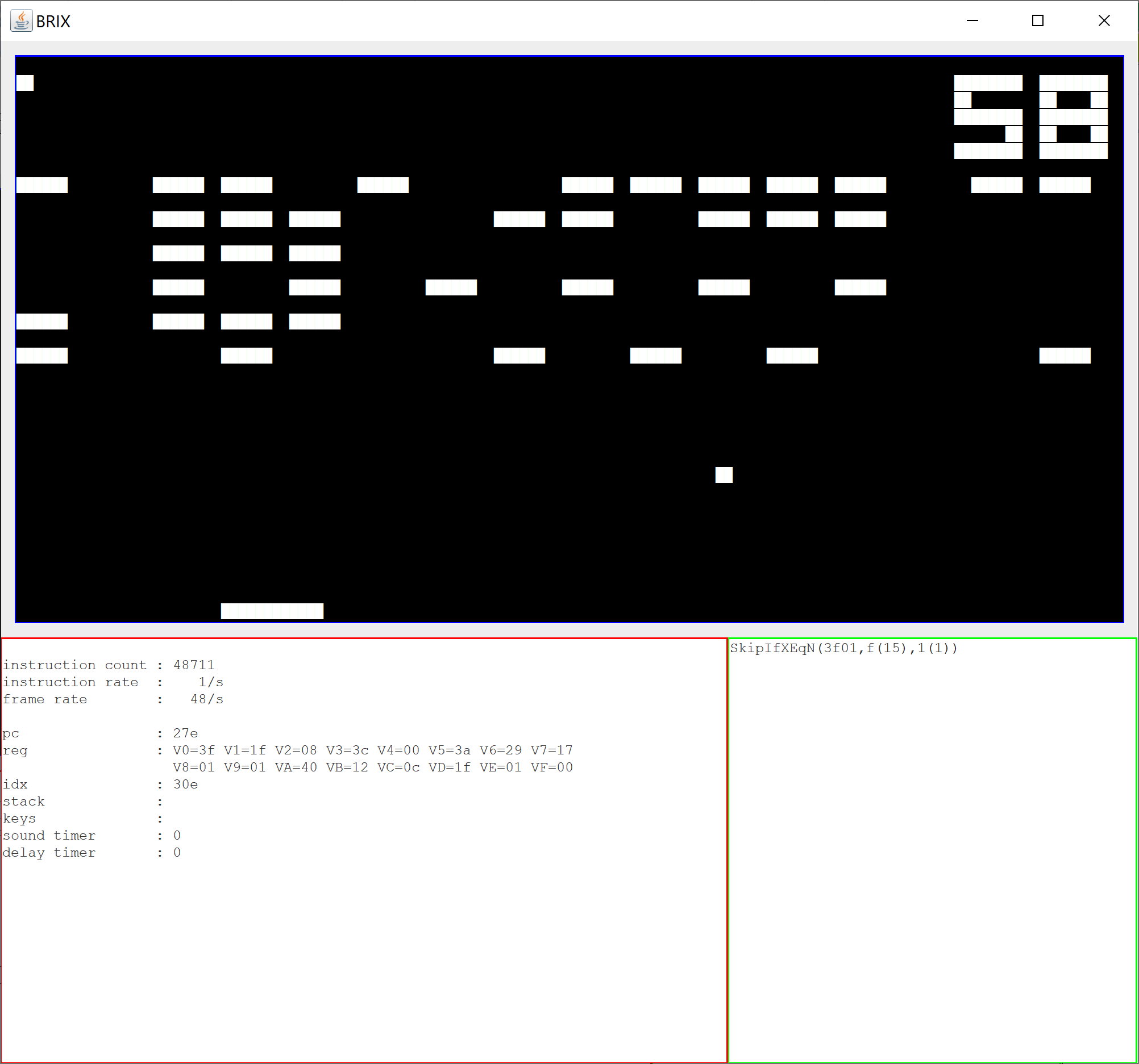
If you are interested, then I have a realistic Verilog simulation of the device so you can use it in your Verilog projects to send and receive data to the simulation too. I’ve used the U245R simulation in my CHIP-8 emulator test program that runs on top of my simulated Verilog CPU model. This allows the CHIP-8 program to communicate with a simple graphics terminal I’ve written.
UM245R velilog model: https://github.com/Johnlon/spam-1/blob/master/verilog/uart/um245r.v
Demo test program: https://github.com/Johnlon/spam-1/blob/master/verilog/uart/test.v
I’ll hopefully do a separate video on that.
Final Word of Warning
Bear in mind that if you are prototyping you may be taking a risk with whatever you connect your project to like your expensive laptop.
If you have a short anywhere in your project then it will short the USB port of whatever you connect it to. That might hurt your PC, then again it might not, but do you want to take the chance?
I give this warning because I actually did this by accident, and it freaked me out that I might have damaged my laptop.
Windows 10 popped up a scary warning that there had been an over-current on the USB port and said I had to restart the machine.
Thankfully once I had done a restart all was ok - but you might not want to take the risk even if your PC has protection.
Perhaps if you put a powered USB hub in between your project and your precious home computer then that might protect your computer - I dunno.
I've already had one accident I am definitely NOT going to routinely use USB power via this UART in future. In fact, I have bought a USB Isolator to make life a little safer. https://www.ebay.co.uk/itm/293838063896
It is based on the ADUM3160 which uses induction decouplers to make the connection more electrically isolated from the PC host. This device passes at most 200mA and has short circuit protection.
-
Github Design Documentation Updated
01/13/2021 at 19:07 • 0 commentsAt long last I've updated github to match the actual state of the project https://github.com/Johnlon/spam-1/tree/master.
Still some details to fill in but all the prior design stuff is pushed out of the way now and lots of up to date stuff added.
-
Chip8 means I need a SPAM-1 "C" Compiler after all
01/03/2021 at 22:22 • 0 commentsIt is with some regret that I have to admit that a cross compilation from Chip 8 is tricky.
Looks like I have to write an interpreter / emulator after all. This is necessary because of the need to mess around with direct memory addresses in Chip-8.
I'm going to write interpreter in SPAM "C" and what this means is that I'm back working on the SPAM "C" compiler. The big change is that I need to upgrade the SPAM "C" compiler from 8 bit to 16 bit Integers. I spent age's trying to decide whether and how to support 8 and 16 bit ints but in the end decided to switch entirely to 16 bits and then work out how to add 8 buts back into the necessary ops. The shorter int would be used most of the time in programs like Chip8 emulation however 16 bits it also needed as the Chip8 program counter is 12 bits and the Chip8 Index register is also 12 bits. So if I do everthing as 16 bits to start with then I can optimise 8 bits back into the compiler. For now I'm declaring everything as "uint16".
It's a bit of a bummer as the ALU can do all 8 bit maths ops in a single clock cycle but even a 16 bit shift takes many more cycles and I haven't yet worked out a 16 bit multiply or divide.
I will add maths ops to SPAM 'C' as the needs of the Chip8 emulator dictate.
In retrospec I'l have to review whether I should have trier retargeting GCC at SPAM-1. I did read around this but the documentation I found suggested that it was a hard thing to do. On the other hand building SPAM 'C' isn't a walk in the park either. It's been educational but also a lot of head scratching and late nights.
----
Later ...
I spent a while reading up on retargeting a compiler to SPAM-1. One page ...
https://stackoverflow.com/questions/8696229/how-to-create-a-c-compiler-for-custom-cpu
led me here ...
http://www.compilers.de/vbcc.html
I will check this out too.
Decisions decisions.
-
SPAM-1 goes CHIP-8
12/24/2020 at 15:54 • 0 commentsSo having gotten my SpamCC compiler working I then realised that perhaps it would be a better idea to start with a CHIP-8 compiler or cross-compiler.
![chip8.png]() The benefit of going after CHIP-8 is the availability of existing software, ie retro-games, and CHIP-8 is really simple with only 35 opcodes.
The benefit of going after CHIP-8 is the availability of existing software, ie retro-games, and CHIP-8 is really simple with only 35 opcodes.So I spent a few hours writing a CHIP-8 emulator to learn more about CHIP-8 and you can see the results in my github repo.
The upshot is that I think a compiler is actually pretty feasible.
A cross-compiler from CHIP-8 bytecode where I dont have the source is also pretty easy most of the time though there will be complications for a few games because of the way instructions are aligned in them. In CHIP-8 every instruction is 2 bytes wide and most of the time the instructions are aligned at an even memory address so it's easy to disassemble the code passing across it linearly. However, the occasional program doesn't align to even addresses so for these one would need to recursively disassemble the code by walking each of the jump operations to see where one ends up. This is feasible except for the Bxxx operation which can jump to a calculated address and this is a bit of a show stopper I think. Fortunately, I haven't seen use of Bxxx and there are plenty of games that do align to even addresses. Also, if I can get the source for a game then that overcomes the disassembly & alignment issue entirely.
Anyway - next step will be to map this into my Verilog simulation to see the simulated SPAM-1 running a game (slowly no doubt) and then get back to the hardware build...
PONG ...
![PONG]()
BREAKOUT ...
-
Further Compiler Enhancements
12/05/2020 at 06:23 • 0 commentsI need to be able to return values from functions. So I had to make a change.
I could have used a "return" statement, but decided instead to extend the function arguments to include "inout" parameters instead.
This allows me to return zero or more value from a function call by marking the relevant params as "out". Technically are "inout" when marked in this manner.
Below I pass 'A' into the call tree and the value is incremented in the function 'depth2' changing it to a 'B'; which we expect to be printed once control returns to the main function.
fun depth2(b1 out) {
 var b1 = b1 + 1;
}

fun depth1(a1 out) {
 depth2(a1)
}

fun main() {
 var arg1 = 'A';
 depth1(arg1)
 putchar(arg1)
}
The Assembler is shown below.
Everything wth a ';' is a comment so there are 36 instructions to implement the above program.
The "EQU" block defined constants for the addresses in RAM for temporary values and for function arguments and also variables used in the program.
The names of these constants map to the static path in the program where the variable can be found.
No stack is used at the moment so all calls and return addresses are recorded in RAM variables allocated to each function. What this aproach means is that the execution is fast at the expense of not being able to safely have functions called recursuvely; ie no "reentrant" functions.
If I retain this calling convention as the default and call it the "variable" calling conventions, then I can introduce a second calling convention called "stack" for those few cases where reentrant functions are needed. The function declaration would signal when it wants one or the other.
root_function_depth2___VAR_RETURN_HI: EQU 0 root_function_depth2___VAR_RETURN_LO: EQU 1 root_function_depth2___VAR_b1: EQU 2 root_function_depth1___VAR_RETURN_HI: EQU 3 root_function_depth1___VAR_RETURN_LO: EQU 4 root_function_depth1___VAR_a1: EQU 5 root_function_depth1___VAR_blkExprs2: EQU 6 root_function_main___VAR_RETURN_HI: EQU 7 root_function_main___VAR_RETURN_LO: EQU 8 root_function_main___VAR_arg1: EQU 9 root_function_main___VAR_blkExprs2: EQU 10 0 PCHITMP = < :ROOT________main_start 1 PC = > :ROOT________main_start ; (0) ENTER root_function_depth2 @ function root_function_depth2___LABEL_START: ; (1) ENTER root_function_depth2 @ statementEqVarOpConst 2 REGA = [:root_function_depth2___VAR_b1] 3 REGA = REGA + 1 4 [:root_function_depth2___VAR_b1] = REGA ; (1) EXIT root_function_depth2 @ statementEqVarOpConst 5 PCHITMP = [:root_function_depth2___VAR_RETURN_HI] 6 PC = [:root_function_depth2___VAR_RETURN_LO] ; (0) EXIT root_function_depth2 @ function ; (0) ENTER root_function_depth1 @ function root_function_depth1___LABEL_START: ; (1) ENTER root_function_depth1 @ functionCall ; (2) ENTER root_function_depth1 @ blkExprs ; (3) ENTER root_function_depth1 @ blkVar 7 REGA = [:root_function_depth1___VAR_a1] ; (3) EXIT root_function_depth1 @ blkVar ; assign clause 1 result to [:root_function_depth1___VAR_blkExprs2] = a1 8 [:root_function_depth1___VAR_blkExprs2] = REGA ; assigning result back to REGA 9 REGA = [:root_function_depth1___VAR_blkExprs2] ; (2) EXIT root_function_depth1 @ blkExprs 10 [:root_function_depth2___VAR_b1] = REGA ; set return address variables 11 [:root_function_depth2___VAR_RETURN_HI] = < :root_function_depth1___LABEL_RETURN_1 12 [:root_function_depth2___VAR_RETURN_LO] = > :root_function_depth1___LABEL_RETURN_1 ; do jump to function 'depth2'' 13 PCHITMP = < :root_function_depth2___LABEL_START 14 PC = > :root_function_depth2___LABEL_START ; return location root_function_depth1___LABEL_RETURN_1: 15 REGA = [:root_function_depth2___VAR_b1] 16 [:root_function_depth1___VAR_a1] = REGA ; (1) EXIT root_function_depth1 @ functionCall 17 PCHITMP = [:root_function_depth1___VAR_RETURN_HI] 18 PC = [:root_function_depth1___VAR_RETURN_LO] ; (0) EXIT root_function_depth1 @ function ; (0) ENTER root_function_main @ function ROOT________main_start: root_function_main___LABEL_START: ; (1) ENTER root_function_main @ statementVar 19 [:root_function_main___VAR_arg1] = 65 ; (1) EXIT root_function_main @ statementVar ; (1) ENTER root_function_main @ functionCall ; (2) ENTER root_function_main @ blkExprs ; (3) ENTER root_function_main @ blkVar 20 REGA = [:root_function_main___VAR_arg1] ; (3) EXIT root_function_main @ blkVar ; assign clause 1 result to [:root_function_main___VAR_blkExprs2] = arg1 21 [:root_function_main___VAR_blkExprs2] = REGA ; assigning result back to REGA 22 REGA = [:root_function_main___VAR_blkExprs2] ; (2) EXIT root_function_main @ blkExprs 23 [:root_function_depth1___VAR_a1] = REGA ; set return address variables 24 [:root_function_depth1___VAR_RETURN_HI] = < :root_function_main___LABEL_RETURN_2 25 [:root_function_depth1___VAR_RETURN_LO] = > :root_function_main___LABEL_RETURN_2 ; do jump to function 'depth1'' 26 PCHITMP = < :root_function_depth1___LABEL_START 27 PC = > :root_function_depth1___LABEL_START ; return location root_function_main___LABEL_RETURN_2: 28 REGA = [:root_function_depth1___VAR_a1] 29 [:root_function_main___VAR_arg1] = REGA ; (1) EXIT root_function_main @ functionCall ; (1) ENTER root_function_main_putcharN_arg1_ @ statementPutcharName root_function_main_putcharN_arg1____LABEL_wait_3: 30 PCHITMP = <:root_function_main_putcharN_arg1____LABEL_transmit_4 31 PC = >:root_function_main_putcharN_arg1____LABEL_transmit_4 _DO 32 PCHITMP = <:root_function_main_putcharN_arg1____LABEL_wait_3 33 PC = <:root_function_main_putcharN_arg1____LABEL_wait_3 root_function_main_putcharN_arg1____LABEL_transmit_4: 34 UART = [:root_function_main___VAR_arg1] ; (1) EXIT root_function_main_putcharN_arg1_ @ statementPutcharName 35 PCHITMP = <:root_end 36 PC = >:root_end ; (0) EXIT root_function_main @ function ; (0) ENTER root @ comment ; // END COMMAND ; (0) EXIT root @ comment root_end: 37 END -
SPAM-1 'C' Compiler - good progress
11/30/2020 at 19:25 • 0 commentsHot on the heels of writing an assembler I decided to take my learning and have a go at a higher level language with C-family syntax.
To be honest the syntax so far looks more like groovy (or even Kotlin) , because of the lack of typing and the use of the "var" keyword and the "main()" function approach looks like Kotlin.
This is being written in Scala because it's a great language for this kind of thing due to its pattern matching and also it's Parser Combinator library which makes parsing a breeze (mostly).
An example of a countdown program is shown below.
The steps in the automated tests are
- compile the "SPAM-C" code into Asm files
- assemble the generated Asm file into ROM images
- run the ROM images in the verilog simulator
These steps happen automatically in the test and this has helped spot loads of potential issues along the way.
SPAM-C code .....
def main() {
     var a=10;
     while(a>0) {
         var a=a-1;
         putchar(a)
     }
 }
The compiler spits out this assembler which is then assembled and the verilog simulator invoked so I get to see the program running too.
root_function_main_a: EQU 0 ; (0) ENTER root_function_main @ function ; (1) ENTER root_function_main @ statementVar [:root_function_main_a] = 10 ; (1) EXIT root_function_main @ statementVar ; (1) ENTER root_function_main_whileCond1 @ whileCond root_function_main_whileCond1__2__check: ; (2) ENTER root_function_main_whileCond1 @ condition REGA = [:root_function_main_a] REGA = REGA PASS_A 0 _S ; (2) EXIT root_function_main_whileCond1 @ condition PCHITMP = <:root_function_main_whileCond1__2__top PC = >:root_function_main_whileCond1__2__top _GT PCHITMP = <:root_function_main_whileCond1__2__bot PC = >:root_function_main_whileCond1__2__bot root_function_main_whileCond1__2__top: ; (2) ENTER root_function_main_whileCond1 @ statementEqVarOpConst REGA = [:root_function_main_a] REGA = REGA - 1 [:root_function_main_a] = REGA ; (2) EXIT root_function_main_whileCond1 @ statementEqVarOpConst ; (2) ENTER root_function_main_whileCond1_putcharN @ statementPutcharName root_function_main_whileCond1_putcharN__wait_3: PCHITMP = <:root_function_main_whileCond1_putcharN__transmit_4 PC = >:root_function_main_whileCond1_putcharN__transmit_4 _DO PCHITMP = <:root_function_main_whileCond1_putcharN__wait_3 PC = <:root_function_main_whileCond1_putcharN__wait_3 root_function_main_whileCond1_putcharN__transmit_4: UART = [:root_function_main_a] ; (2) EXIT root_function_main_whileCond1_putcharN @ statementPutcharName PCHITMP = <:root_function_main_whileCond1__2__check PC = >:root_function_main_whileCond1__2__check root_function_main_whileCond1__2__bot: ; (1) EXIT root_function_main_whileCond1 @ whileCond PCHITMP = <:root_end PC = >:root_end ; (0) EXIT root_function_main @ function root_end: END -
SPAM-1 Assembler
11/14/2020 at 19:54 • 0 commentsDecided to get on with writing an assembler for SPAM-1 and use this as an opprtunity to learn about writing grammars.
My previous effort at writing an Assembler was way back when I was experimenting with using Google sheets for the assembler for my Logisim model. At that time I was shy of speaking on camera so I recorded a silent video of using that software. See "Prequel 1" below. Attempting to use Google sheets for the toolchain is quite limiting obviously. I turned to using Icarus Verilog to te idea of using Google sheets for anything more was bust. So I've reverted to proper dev tools and Linux.
My first attempt recently was using Antlr4 to write a grammar and parser and I spent a couple of days on this. But I became quickly frustrated with the approach. I found it pretty difficult to get the software to do what I wanted and while there's a lot of documentation but it didn't help me much when I had problems. Also I didn't particularly like the approach of writing a text file grammar and then having to compile it into code. I spent quite a few years programming in Scala and I was aware of better alternatives.
So, I switched to using scala and scala's "parser combinators" to build an assembler. Parser combinators are just a library built into the SDK that provide some fancy Scala operator syntax to allow the building of Lexer/Parsers really easily, and without all the hassle of Antlr and the entire thing is done in the scala language itself and not two different modes like Antlr. This aproach shortened the dev cycle and the strong type system in scala helped to direct the work and avoid subtle type related bugs. I also found a bunch of useful parser combinator stuff to use for inspiration such as a 6502 parser that I could learn from.
Every operation in SPAM-1 is an assignment like REGA=REGB+REGC and the assembly language looks like this ...
; define a constant called SOMEVAR using a constant expression
; forward references to label addresses are permitted

SOMEVAR:    EQU ($0100 + %1010 + $f + 1+2+(:LABEL2+33)) ; some arbitrarily complicated constant expression

; grab the top and bottom bytes of the constant SOMEVAR into two constants

TOPBYTE:    EQU <:SOMEVAR                        ; top 8 bits into TOPBYTE
BOTBYTE:    EQU >:SOMEVAR                        ; bottom 8 bits into BOTBYTE

; demo setting registers to constants

            REGA = $ff                          ; set A to the constant hex ff but do not set processor status flags
            REGB = $ff    _S                    ; set A to the constant hex ff and set the processor status flags

; registers can be set to results of ALU operations

LABEL1:     REGA = REGB   _C_S                  ; if Carry is set then update A to value of B and set the flags
            REGA = REGB
            REGA = REGA A_PLUS_B REGC           ; set A = A + B but do not set flags
            REGA = REGA + REGC                  ; set A = A + B but do not set flags            REGA = REGB A_MINUS_B [:SOMEVAR]    ; set B to the data at RAM location :SOMEVAR
LABEL2:
            REGA = :TOPBYTE                     ; set A to the constant

; unconditional jump to whatever SOMEVAR was pointing to

            PCHITMP = :TOPBYTE                  ; prepare the top PC register for a jump
            PC      = :BOTBYTE                  ; execute the jump to the location defined by {TOPBYTE:PCHITMP}

END
You can see the code for the assembler here .. https://github.com/Johnlon/spam-1/tree/master/verilog/assembler
The grammar is pulled together by the Parser class https://github.com/Johnlon/spam-1/blob/master/verilog/assembler/src/main/scala/Parser.scala
Next revision will be to have it write the ROM files for the Verilog simulation so I can double check the solution. I've written some automated scalatest tests so I'm hopeful.
Have fun.
===
Below is my eariest effort at a YT video :)
-
Triple Port Register Patterns
10/29/2020 at 05:53 • 0 commentsShort video covering the register file pattersn I've used in the CPU.
Extension of the previous video ...
SPAM-1 - 8 Bit CPU
8 Bit CPU in 7400 with full Verilog simulator and toolchain

 The benefit of going after CHIP-8 is the availability of existing software, ie retro-games, and CHIP-8 is really simple with only 35 opcodes.