 Ethan Durrant
Tl;dr: Progress for LCD emulation via the GPIO is currently in the research/planning stage, and support of the HD66702 LCD Driver Character ROM is complete.
GPIO Mapping:
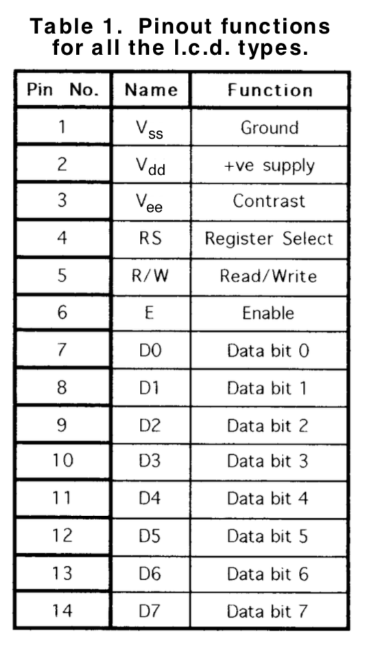
After studying the pinout of a standard Character LCD (shown below) I've got a general idea of how I want them mapped on the 8051's GPIO:
Current plan is as follows:
- Data Bus (D0-D7) mapped to Port 0 for bidirectional data flow.
- D7 on P0.7 is also used as the Busy State output pin in to manage data flow. This will be important, as the emulating 8051 will not be as fast a native LCD Driver chip.
- Register Select (RS) on P1.1
- Read/Write (RW) on P1.0
- Enable (E) on P3.3 allowing use of the 8051's External Interrupt 1 (INT1) in hardware. As the Enable pin is active HIGH and the 8051's External Interrupt is active LOW or transition to LOW, the signal will have to be inverted before fed to P3.3. This will be used so we can handle/save requests from the control MPU/MCU as quickly as possible via an interrupt service routine.
Handling Contrast:
Contrast is an Analog input, and the 8051 has no ADC. The HP LED displays have a Vb input that can be used to strobe the displays with PWM and change the apparent brightness.
One solution could be to use a 555 Timer based circuit to take the analog input and generate a varying PWM brightness output from it. This would also stick with classic components! Who doesn't love a 555?
Multitasking:
To handle the multiple tasks in emulating an LCD Driver the current firmware will need some further modification. Currently the main loop just handles updating the display columns when triggered by a flag set in a Timer Interrupt at 500Hz.
To implement multitasking I plan to have several separate simple "tasks" executing when required, within each "tick" of the main loop, with some tasks only running when given a flag via an Interrupt.
Main tasks are as follows:
- Refreshing display columns from internal display output buffer at a rate of 500Hz. Triggered by flag set in a Timer Interrupt.
- Interpreting commands given from the master MPU/MCU on the GPIO ports and sets the Busy Flag to 1. Triggered by a flag set in an External Interrupt on Enable (E) transition to HIGH.
- Updating and modifying the internal display output buffer based on given commands and system state. Probably be implemented with a state machine of sorts. Manage blinking of the cursor if required.
- Returning any requested data to the master MPU/MCU.
Character ROM:
All three Character ROM codes of the HD66702 are available in the `ascii5x7.c` and `ascii5x7.h` files. Japanese Hiragana can optionally be included alongside any of the ROM codes.
Time:
As much as I'd love to continue developing this soon, I will be away from my humble college dorm workbench for a few weeks, and then will be returning to face an intense Fall Semester of Engineering classes.
Needless to say, time will be limited, but I'll certainly continue development when I can!
Happy Hacking :)
Discussions
Become a Hackaday.io Member
Create an account to leave a comment. Already have an account? Log In.