 Sven Dahlstrand
After a good nights sleep and breakfast, I reached for my wire cutter and cut off the NES connector from the joystick cable. There are five wires inside the cable, color-coded as black, white, blue, green and brown. I had no idea what color corresponded to wich signal. What I do know is the NES controller port pinout, thanks to the hard-working Nesdev community. With that information, I pried open the plug to figure out the relationships between wires and pins.
So, without further ado, I'll present to you my findings. Be careful though: I can't guarantee all Zinger joysticks are wired the same way or using the same colors as mine.
The Zinger plug pinout
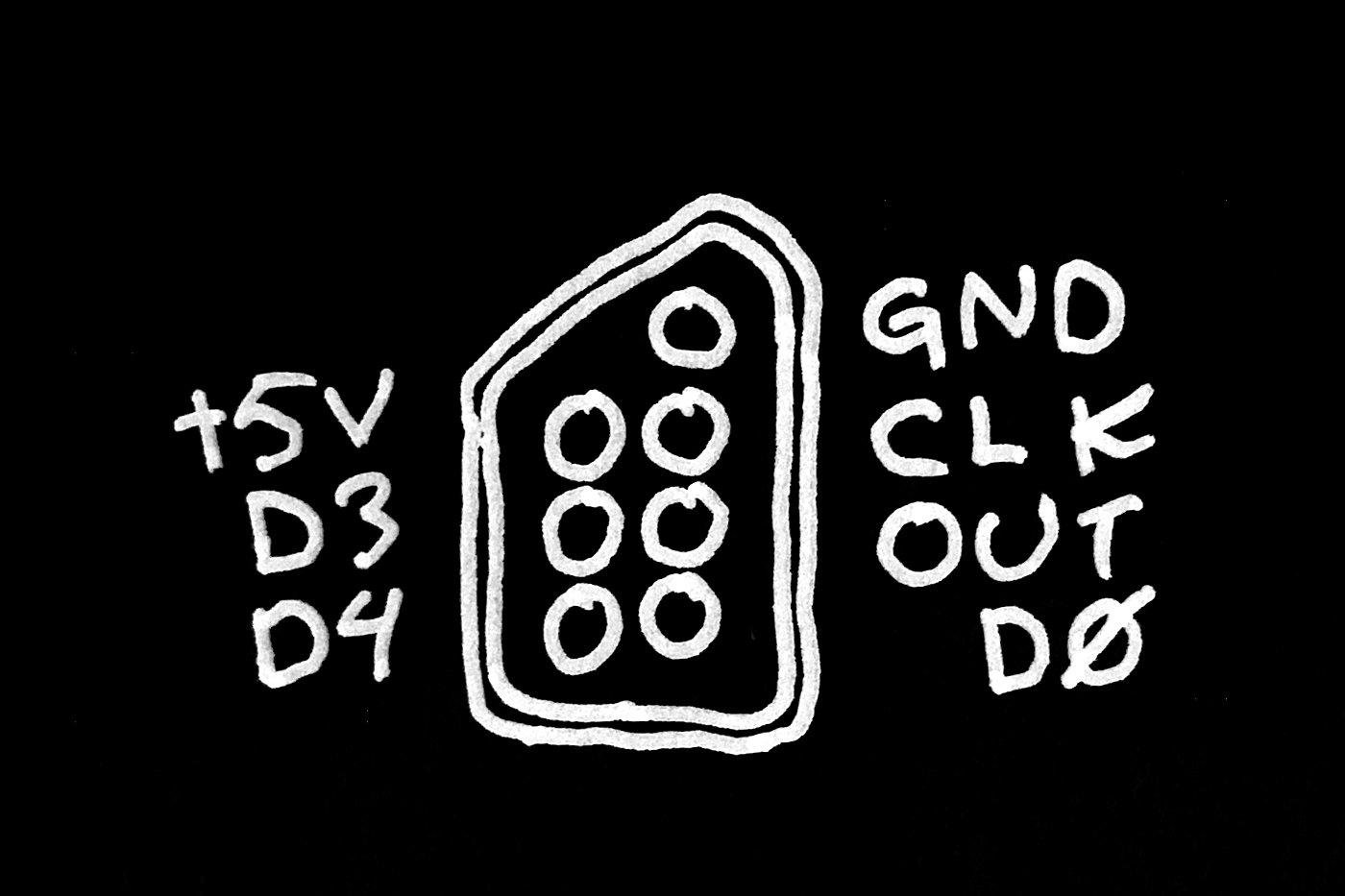
Name | Wire color |
|---|---|
| GND | Brown |
| CLK | Blue |
| OUT | White |
| D0 | Green |
| +5V | Black |
| D3 | Not present |
| D4 | Not present |
Black for +5V and brown for GND? Not the most obvious choices of color if you ask me.
Discussions
Become a Hackaday.io Member
Create an account to leave a comment. Already have an account? Log In.