My first idea was use 6502 CPU or similar because never used Z80 CPU in depth only in theory. But, when I put hands on it, like more and more. Initially I'd used some ideas from http://www.z80.info and basic projects and core from http://www.searle.wales/ (Grant Searle). The simplicity to manage I/O and memory space help organize memory map than a other processor with a single memory mapping for all things, like 6502. The Z80 have two signals to manage IO requests (IORQ) and Memory Requests (MREQ), this signals are enabled/disabled using in/out instructions or ld (move) memory instructions.
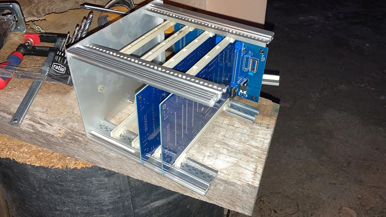
The second step was a design physical layout of main board and how construct a main bus and backplane standard. The backplane system uses 40 pins edge-connector integrated on board similar that used on Expansion bus of Dragon Computer.
The hardware:
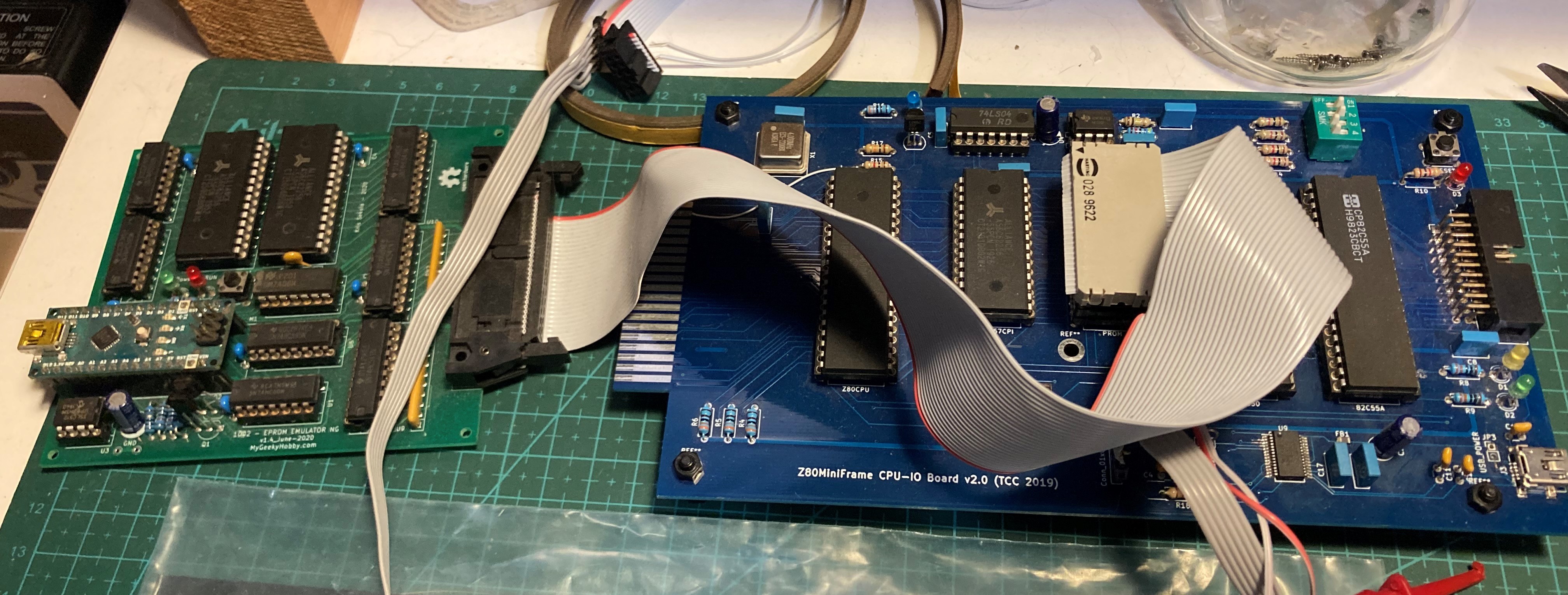
- CPU-IO Board Card: This is a core of system that contains main CPU (Z84C0008PEG) at 4MHz of main clock generated by a 4MHz clock generator, 32KB SRAM and 8KB or 32KB EEPROM, UART 16550 and PIO 82C55. This card can connect directly to USB PC port to able communicate via serial terminal to operate to core monitor system. The latest version can be powered via USB. This board basically are a computer core, can works alone, but their functionalities depends on EEPROM size:
- Core with 8KB EEPROM only works with serial port as a system console.
- Core with 32KB EEPROM can use graphics/sound card and other devices.
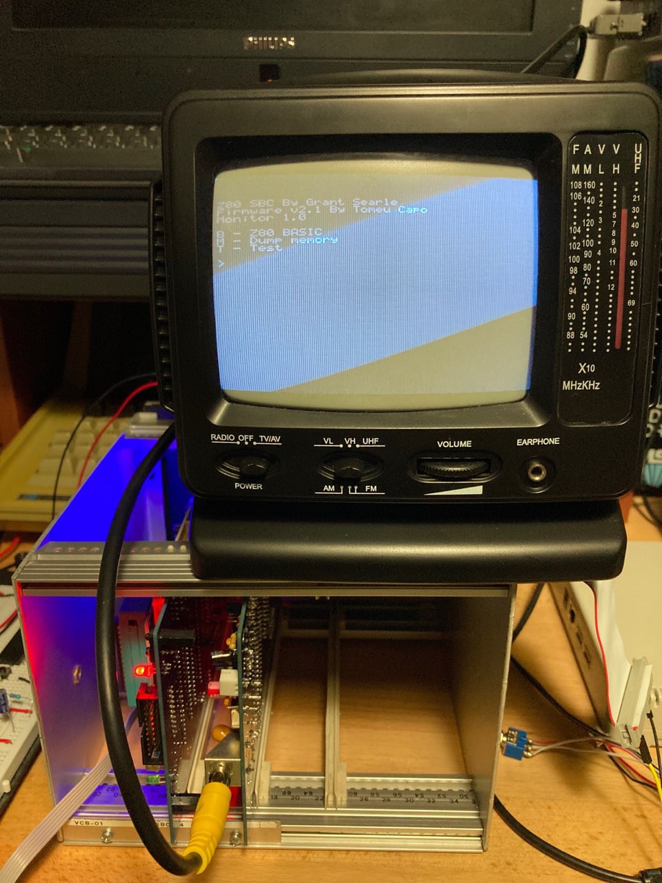
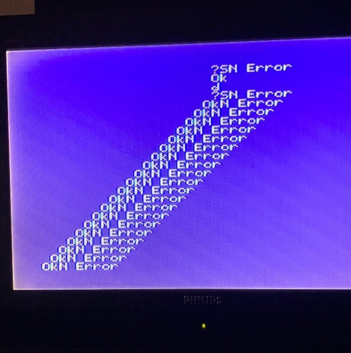
- Graphics and Sound Card: This part that contains a Video Display Processor (TMS9918A) and Programmable Sound Generator (AY-3-8910). The VDP needs a crystal with a critical value like (10.738635MHz) that generate sync signals this is very important thing to use TMS9918A. I tested other crystals without success, and finally use recommended value by datasheet. One other image sync issues that produced by using some PAL color CRTs the image was not seen correctly with clear synchronization problems. Finally works with Philips Monochrome CRT 12". This board have an additional IO Port connector that provides the PSG.
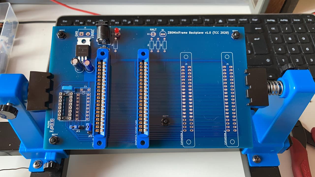
- The backplane: I working on it, now. I design a simple backplane with a 4 expansion 40 pos. edge female connectors and main power supply. Additionally backplane is have an additional decoding TTL ICs to select more devices are connected to expansion ports.
The software:
First I began with zmac (http://48k.ca/zmac.html) Macro Cross Assembler Compiler to compile my first tests on IO ports and my first "hello, world" that blinks a simple LED. Next get a bootloader Grant Searle core program and test it into my core system. In the Searle bootloader don't uses my UART IC and needs adapt and create new IO routines that works with 16650 UART.
Now separate all code to different asm files and linked after with LD80 linker.
 Tomeu Capó
