Specification
- expected linear speed for a 40mm wheeled robot -> [10mm/s; 1m/s]
- transformed into wheel rotational speed -> [XXRPM; XXRPM]
To match spec, we need to paid attention motor's type. For our application, three type of motor would have been OK to replace Dynamixel servo: stepper motor, brushless motor or DC geared motor. Similarly, several angular position sensors would have fit our needs:
- Quadrature Hall Sensors, they produce analog signal proportional to magnetic field
- 1 or more Logical Hall Sensors (at least 2 are needed to estimate direction). They produce a logical high state when sensors reach magnetic threshold corresponding to a locally magnetized area on the ring
- Magnetic encoders
- Optical encoders
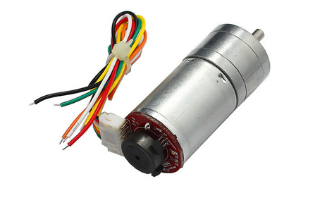
In order to keep costs as low as possible, widely available DC geared motors with 2 logical hall sensors are used for this project.

Motor and Encoder sizing
Characteristics
- max speed: RPM
- voltage: 6V
- torque: largely enough
- reduction gear: 1:850
NB: the reduction factor must be quite important, because angular position resolution depends on this value, enabling low rate control.
Motor piloting board
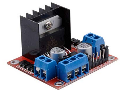
To power motors the popular double H-bridge L298N board is selected. Documentation an tutorial for this board are widely available on the web.

This board only support up to 2A per channel while our motors could demand up to XXA. In order to use safely this board, current needs to be monitored.
Current sensing
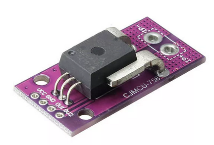
As detailed above, sensors will be used to monitor current and prevent overcharge on L298N. I choose the CJMCU-758 with ACS758LCB-050B-PFF-T that allows bidirectional current measurements.

 matop
matop
Discussions
Become a Hackaday.io Member
Create an account to leave a comment. Already have an account? Log In.