Close
0%
0%

FlipClock

An Arduino-based graphical “flip clock”. Bonus faces because there’s room. Really minimal enclosure.

Public Chat
Similar projects worth following
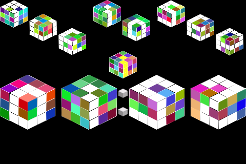
I'd had the idea for a graphical flip clock for a while (run-length encode half-digit foreground/background data, draw every n-th row to get the look of a tipped split flap) but it was on the back burner. Then I found a pretty nice 3.5” 320x480 colour LCD (ILI948x driver) on a local market website. After implementing the clock I found I had room in the sketch and was inspired by the colourfulness of the LCD, so slapped in some other faces based on code from earlier projects; a cubist clock, a triangle clock and a pong clock.
The LCD is a shield socketed onto a blank intermediate shield with RTC and push-buttons directly attached. The intermediate shield is socketed to a Uno, creating a quite thick "sandwich".

I went with an ultra minimal enclosure, front and back clear acrylic plates.

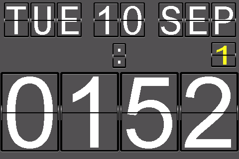
The main clock display is the day, date and month in smallish flip-style digits across the top of the LCD (landscape mode).  The time is in big digits across the bottom. As a bonus, across the middle there’s a blinking/flipping colon and also a coloured digit indicating the number of days until I need to put out either the rubbish bin (red) or the recycling (yellow). It’s alternate weeks and I keep forgetting (this display is optional).  

The time digits change with a detailed 3-step animation (top flap at 41°, 90° and 131°).  The angles come from skipping every 4th row of the digit data, so it’s acos(3/4)=41°, close enough to 45°!

The LCD inspired me to add in some additional clock “faces”:

CubeClock

The LCD colours are appealing, so I experiment with coloured cubes. The look is based on this font www.dafont.com/kubics-rube.font

Triangle Clock

An adaptation of an eariler project with a triangulated irregular network (TIN) style face, more pretty colours.

PongClock

There was a little program memory left, so I squeezed in a very simple Pong Clock, again using code from an earlier project.

The sketch uses all but around 100 bytes of the Uno’s program storage space.

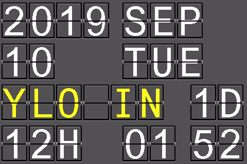
There are two push-buttons, Set and Adj. Pressing Adj from time display cycles through the faces (including a pseudo-face which randomly cycles through faces). Pressing Set from time display goes to the configuration screen. This uses the flip clock look. As well as setting the date and time it configures the red/yellow bin cycle (or none)

The clocks use a simple automatic DLS adjustment class which takes a table of start/end dates.

The LCD shield uses an ILI948x driver.  As always, the trick is finding some code which successfully initialises the display (including orientation).  The only other interaction is a) setting a “window” on the screen and b) filling it with colour data.

The viewing angle is fairly important, from the wrong angle the display is quite washed out.

This shield has a built-in SD-card reader, but no touch screen.  Fortunately that leaves pins 10,11,12,13 and A5 free. I connected SET/ADJ push-buttons to 10 & A5 and used 11 & 12 as SDA/SCL for a software I2C to the DS3231 real time clock module.

There was a lot of software in this project so when the time came to go from prototype to final assembly I decided to go to the other extreme and keep it as simple and minimalistic.   It starts with a blank stackable shield. This gave me access to the pins I needed for the RTC and the two switches. I mounted all directly to it. The LCD shield goes on top, and Uno underneath to create a quite thick sandwich.  This sandwich would actually have been enough, since it stands up OK. But I decided to add some protection in the form of two laser-cut clear acrylic plates. The Uno is attached to the back plate. The front plate is attached to the back plate with stacks of standoffs.

There is no backlight control and the thing is quite bright. To keep the build simple, there’s no LDR to sense ambient light and dim the display. Instead, there’s a bit of a hack in the sketch to optionally blank it between selected hard-coded hours (eg 7pm-7am). All that does is make the display black, but there’s still a glow - the copper tape is an attempt to reduce this light leakage.  I plan a separate project with an LDR and a relay…

Video

Flickr album (pictures, with captions!)

Flickr Album

Screen shots

Photographing the screen was tricky. I modified the sketch to optionally send the LCD commands and data out the serial port.  I wrote a small Python program to read in a file of the serial output and re-create the image as a PNG.
FlipClock.zip

Zipfile of *original* sketch. Latest is on GitHub

x-zip-compressed - 50.61 kB - 08/16/2019 at 03:13

Download

  • Mega support etc

    Mark Wilson05/05/2023 at 03:16 0 comments

    UPDATE 5th May 2023:

    The sketch is now on GitHub (https://github.com/funnypolynomial/FlipClock, original remains here as a zip). This includes:

    • Support for Arduino Mega/Mega 2560 (in addition to Uno)
    • Digit wrap is now correct - 10's of minutes going from :59 to :00 won't flash :60
    • Optional blank flap in 12-hour mode. " 307" vs "0307", see ENABLE_BLANK_TENS in Config.h
    • Automatic DLS adjustment is off by default, see ENABLE_AUTO_DLS in Config.h
    • The LCD driver has support for variants the otherwise jumble the screen, see LCD_FIXED_ORIGIN in ILI948x.h

View project log

Enjoy this project?

Share

Discussions

barrow4491 wrote 04/12/2020 at 01:29 point

jim

  Are you sure? yes | no

barrow4491 wrote 04/12/2020 at 01:29 point

mark, thanks for that

  Are you sure? yes | no

barrow4491 wrote 04/11/2020 at 08:35 point

Thanks for the prompt response, I am a bit of a newbie with Arduino and am probably doing something stupid. 

I don't know whether it is the correct way to do it, but i am using the "add file" command when the compiler comes up with  the message "ILI948x.h: no such file or directory" for example and it adds a tab of that name and so on.

When all the files are added this way it will not upload an comes up with the error regarding unable to load to Arduino Uno

I really want to know how to correctly add the .h files to the sketch so it will compile. When I unzip your file it just gives me a list of .h and .cpp files with one .ino file (FlipClock)

Thanks in advance

jim

  Are you sure? yes | no

Mark Wilson wrote 04/11/2020 at 22:45 point

It should compile as-is when unzipped, but we should take this off-line. I will msg you.

  Are you sure? yes | no

barrow4491 wrote 04/12/2020 at 01:35 point

Mark ,

I appreciate that, my address is 

barrow4491@gmail.com

Regards

Jim

  Are you sure? yes | no

barrow4491 wrote 04/11/2020 at 05:36 point

I am having a problem with the code, cant find the libraries

can you please advise

  Are you sure? yes | no

Mark Wilson wrote 04/11/2020 at 06:52 point

What libraries?  I don't think it requires any. What error(s) are you getting?

  Are you sure? yes | no

Mark Wilson wrote 11/22/2019 at 00:33 point

See also LDRelay, https://hackaday.io/project/168590-ldrelay

Turns the device off in the evening when the room gets dark, then back on in the morning when it's light!

  Are you sure? yes | no

Jacques G lerner wrote 10/26/2019 at 14:23 point

Thanks Mark for you remarks, you saved me a standing amount of frustration. Never mind about gyros, they're for other project... And thanks for the heads up about DST.  I owe you a beer! Now I'm waiting my hardware. For now I have a beautiful face is iddling 12:00.Let's how it comes with the DS 3231..Last subject, isit possible to change the black and white face for something like a deep blue and white? Your photo, and mine by the way, shows blue but it's black and white. Enough form today. Cheers, man!

  Are you sure? yes | no

Mark Wilson wrote 10/27/2019 at 02:38 point

The blueness is just a artifact of the photo, the lighting and the viewing angle.  You should be able to play around with colours by changing the constants in Leaves.h but some hard-coded colours (like black & white) may've snuck in there. Easy enough to change.

  Are you sure? yes | no

Jacques G lerner wrote 10/28/2019 at 14:39 point

I took a photo as  blue/white effect too. As you say, too much backlight. My "middle board ", the red one, will arrive this week. Is is true that you soldered the DS3231 and brought it to the 3.3v and Ground and then all the remaining wires as per your photo?

  Are you sure? yes | no

Mark Wilson wrote 10/28/2019 at 18:42 point

I'm not getting a "reply" button on your most recent post so I'll have to use this.

I don't know what your DS3231 breakout needs but it's probably 5V not 3.3V.  Check its pin labels.  It's not clear on my photo, I think I may have done the 5V line on the underside.  But also look at Pins.h which has an ASCII schematic.

  Are you sure? yes | no

Jacques G lerner wrote 10/28/2019 at 22:12 point

Thanks, indeed is a 5v (datasheet confirms)  and almost certain you pinched 5v under the "red" board.I just received a protoboard, kind of different of yours but I'll follow your Pins.h to guide my clock.. WIsh me luck, 

  Are you sure? yes | no

Mark Wilson wrote 10/29/2019 at 05:40 point

Good luck. I checked: the proto-board I used distributes 5V and Gnd, no need for a wire underneath the board to power the RTC

  Are you sure? yes | no

drechsler1952 wrote 10/26/2019 at 07:54 point

Hi Mark, thanks for the quick response . I think I have got it. I bought 2 moduls DS3231 and the are fakes. I installed another from an  older project and now it works fine ( + / - ) 2-3 sec/day. 

Other question: is there in the code anywhere the possibility to activate and indicate the actually  number of week of the year instead of the rubbish bin indication. Your comment : " It’s alternate weeks and I keep forgetting (this display is optional)"  

Best Regards

Burkhard

  Are you sure? yes | no

Mark Wilson wrote 10/27/2019 at 02:43 point

There is no code but there is certainly the possibility to change the bin indicator to the week number.  See Clock::updateDate() and config.UpdateBin(); etc.  Hack the bin calcs out (to make room!) and add your own week number calc -- get the date, add up the days in past months, and days into current month, divide by 7.  The display currently shows 1 digit but you could add a second

  Are you sure? yes | no

drechsler1952 wrote 10/25/2019 at 14:30 point

Hi Mark, thanks for sharing this project. I have done it and the animations are really great ! But one thing is fore me not clear: per day the clock went plus ore minus more than 1 minute (depend only from the Arduino board), the DS3231 doesn't matter. I also have tried different. Normally  the DS3231 has a aberration from about 1-2 sec. /month. Do You have any notions ?

Regards

Burkhard

  Are you sure? yes | no

Mark Wilson wrote 10/26/2019 at 04:02 point

Well if you're checking the minute roll-over against another reference you will see some variation, although not a whole minute.  Look at Clock::CheckUpdate().  It only goes to the clock module to pull off the time every 20s or so, and then only updates if the minute has changed. You could try changing checkTimeDuration in Clock.h to say 1000 (1sec) to see if that makes a difference.  If you really care about precise display you could comment out the if (RTC::CheckPeriod...) entirely.

  Are you sure? yes | no

Jacques G lerner wrote 10/18/2019 at 15:50 point

Have already compiled my sketch, so far so good. My rela time clock os one like this one:

https://www.banggood.com/DS3231-AT24C32-IIC-High-Precision-Real-Time-Clock-Module-For-Arduino-p-81066.html?p=4N130123074053201807&utm_campaign=23074053&utm_content=3312&cur_warehouse=CN

my gyroscope is this one::

https://playground.arduino.cc/Main/MPU-6050/

Should that work on your FLipClock or so I need to do some ajustments on the sketch?

I intend to do first an experimental assemble in a breadboard and then, if that's OK will do some welding .

Also I want to know how I can disable the DST as for the first year in many it was decided that we won't have DST this year.

Sorry for the long list of questions but your project is super!

  Are you sure? yes | no

Mark Wilson wrote 10/26/2019 at 04:11 point

It looks like that RTC has a different I2C address.  You will need to change

#define RTC_I2C_ADDRESS 0x68

in RTC.cpp to

#define RTC_I2C_ADDRESS 0x57

No idea about the gyro.  What is that for?  You won't have room for any additional code to interact with it.  My clock does not use a gyro

Re daylight savings.  The code currently only handles New Zealand and USA.  You can define your own table of on/off dates, or disable it by commenting out the

SimpleDLS::SetData(...)

line in FlipClock.ino

  Are you sure? yes | no

Jacques G lerner wrote 10/28/2019 at 14:44 point

Thanks a bunch! Will never spot the change of IDC address. that's a feature not a bug! :-)

  Are you sure? yes | no

gsainton wrote 09/26/2019 at 13:08 point

Hi,

Where may I found the schematic.

Gilles, Newbie

  Are you sure? yes | no

Mark Wilson wrote 09/26/2019 at 21:34 point

Well there's not much to it, it's shields, two buttons and an RTC.

But "PINS.h" in the sketch zip file has an ASCII-art schematic of a sort

  Are you sure? yes | no

Jim wrote 09/25/2019 at 18:06 point

Where did you source the plexiglass?

  Are you sure? yes | no

Mark Wilson wrote 09/25/2019 at 19:28 point

I use Ponoko to do the laser cutting, they provide the materials too.

  Are you sure? yes | no

Stephan.ridel wrote 08/22/2019 at 13:53 point

oh thank you Mark. I havn’t Understand the data pins part and I need to shop a compatible display . By the Way, your 8x8 matrix clock is also a nice project. Using a gyro to change the display is smart !

  Are you sure? yes | no

Mark Wilson wrote 08/22/2019 at 19:05 point

Thanks!  Good luck shopping.

  Are you sure? yes | no

Stephan.ridel wrote 08/21/2019 at 17:20 point

Hi Mark ! Really nice rendering. I was wondering if you can share the display reference for wiring. I see the pin.h file but not able to find the correct pin... many thanks

  Are you sure? yes | no

Mark Wilson wrote 08/21/2019 at 19:26 point

Hi Stephan,

Thanks. Which pin can't you find? 

The LCD shield looks like this one:

https://www.banggood.com/3_5-Inch-TFT-Color-Display-Screen-Module-320-X-480-Support-Arduino-UNO-Mega2560-p-1022298.html?cur_warehouse=CN

The LCD shield connects to the Uno and uses pins 2-9 for data & pins A0-A4 for control.  The only other pins involved are 11/12 for SDA/SCL to the RTC module and A5 and 10 for the push-buttons. Plus of course some Gnd's and +5V's...

let me know if this helps!


  Are you sure? yes | no

Similar Projects

Does this project spark your interest?

Become a member to follow this project and never miss any updates