 Jonathan Bumstead
-
11Box Component Mounting
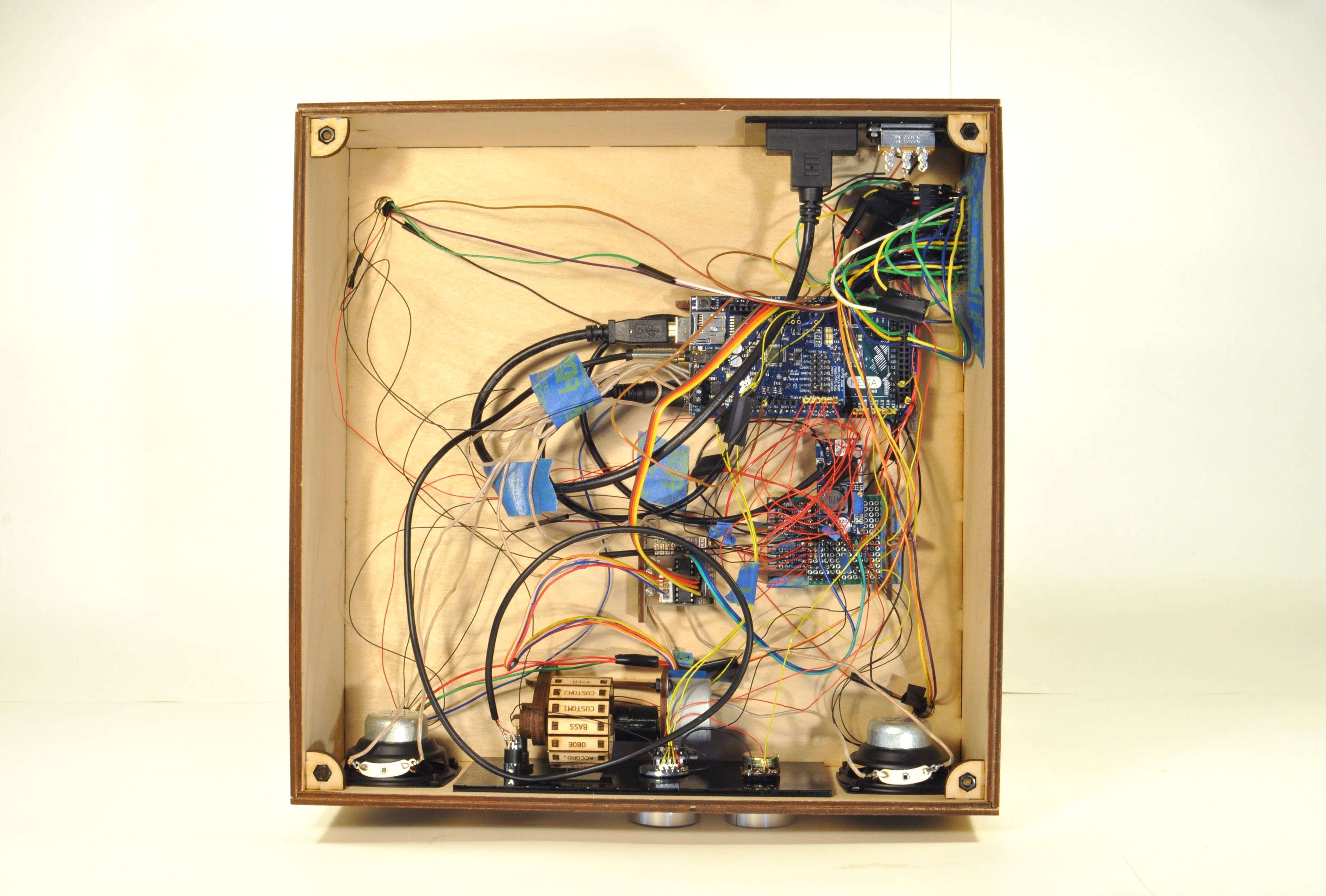
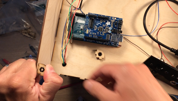
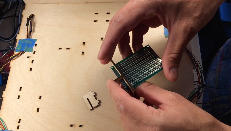
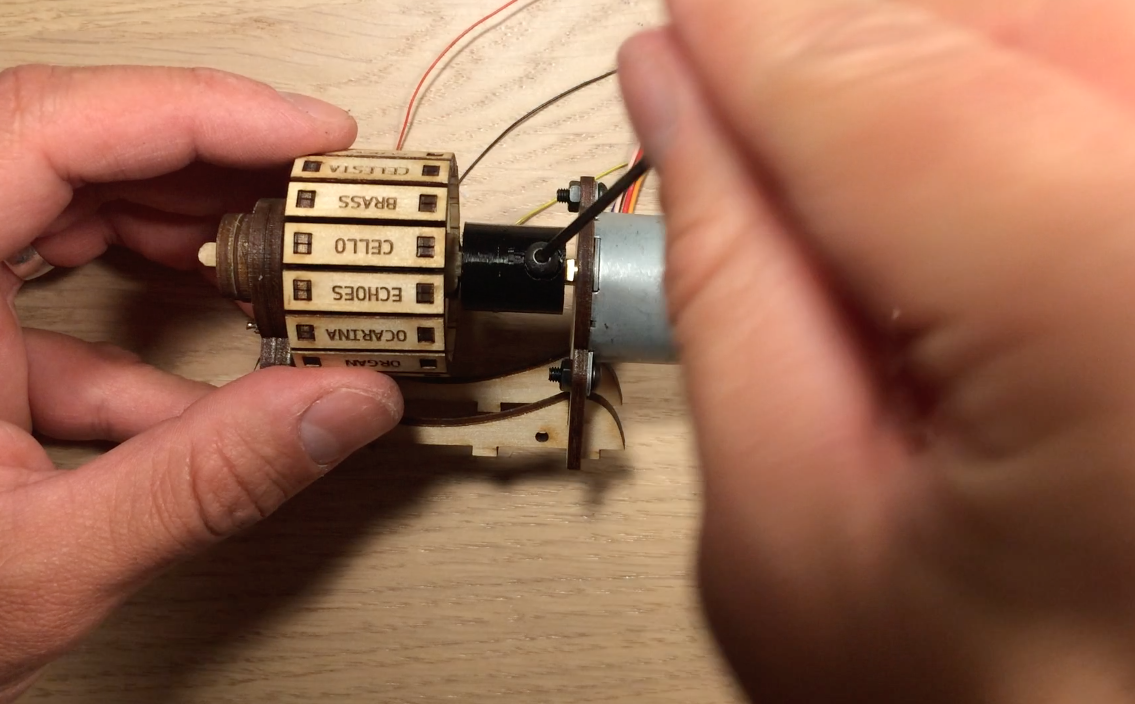
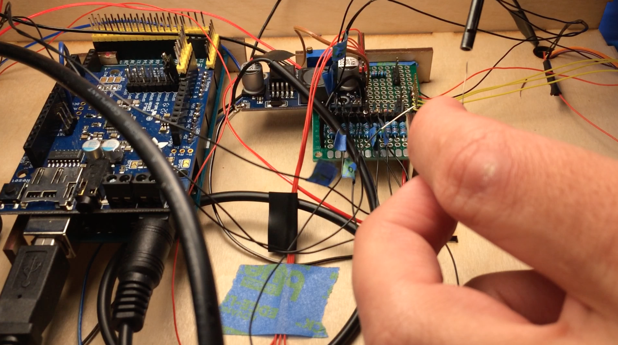
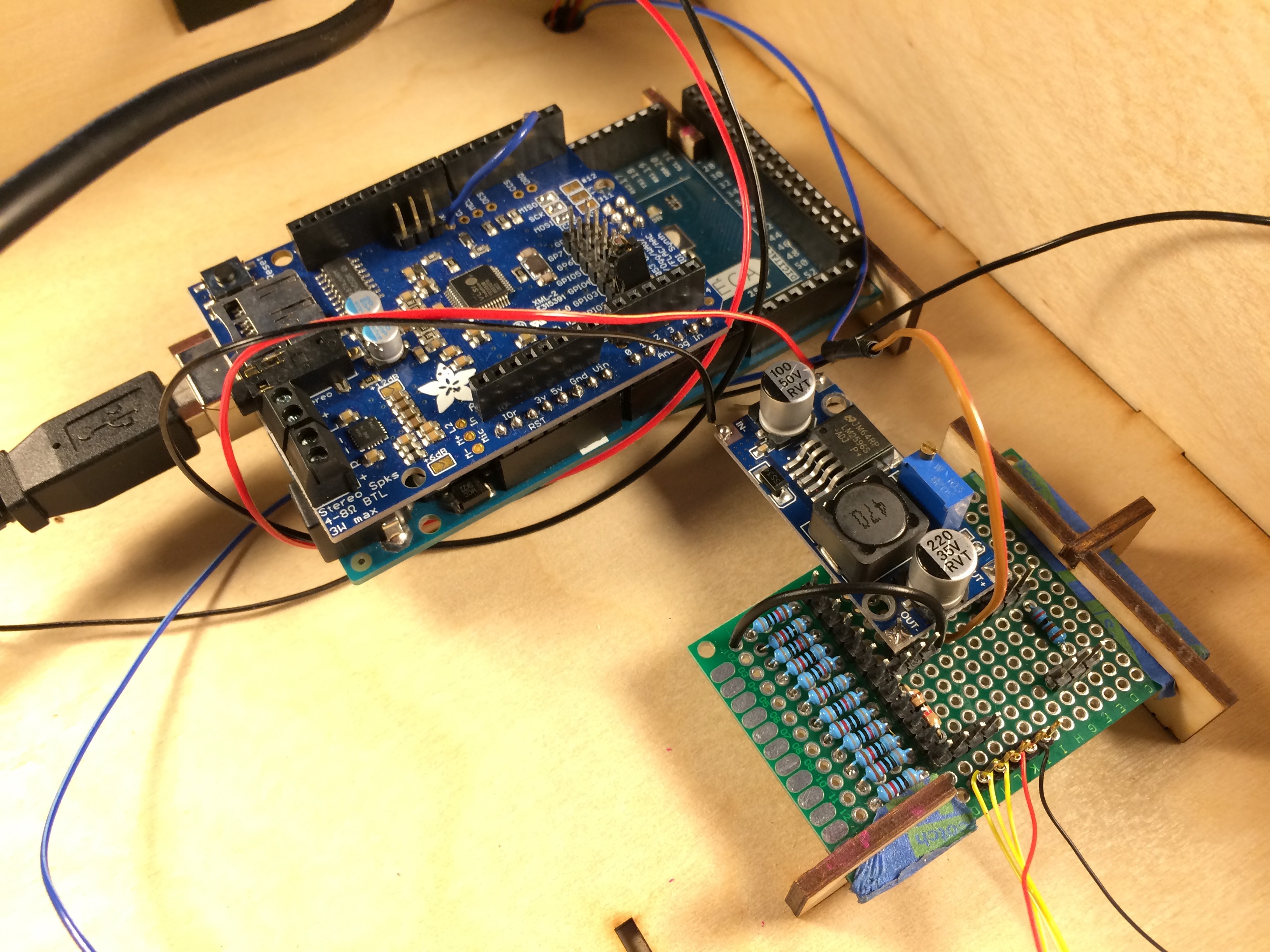
I designed all the electronics to be mounted to the top of the electronics box so that the bottom panel could easily be removed if the electronics needed to be troubleshooted. The Arduino Mega, stepper motor controller, prototype board, and instrument wheel are all pressed into the top of the box using the mounts.
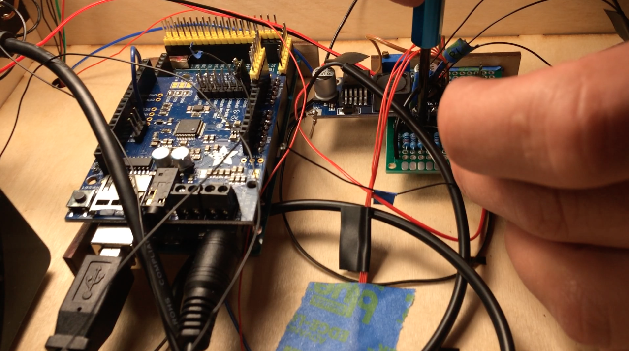
A few lasercut parts slide over the boards as shown in the images above. These parts then press into the holes in the top of the box. All the electrical components shown in the diagram are soldered to the prototype board: transistors for controlling the laser diode modules, resistors for the photoresistor circuit, pins for front panel components. There is a lot of soldering work, so for the second version I designed an upright laser harp PCB.
![]()
![]()
![]()
![]()
![]()
![]()
![]()
![]()
![]()
![]()
![]()
![]()
-
12Front and Rear Panel
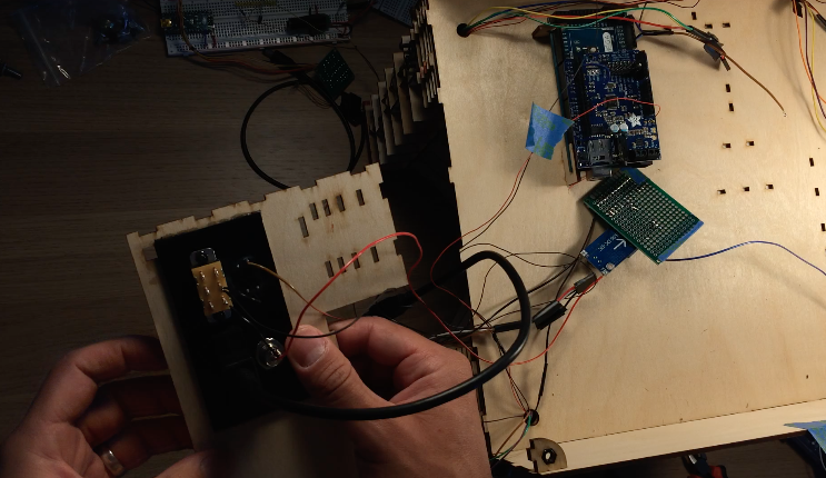
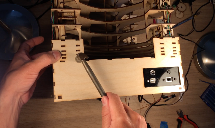
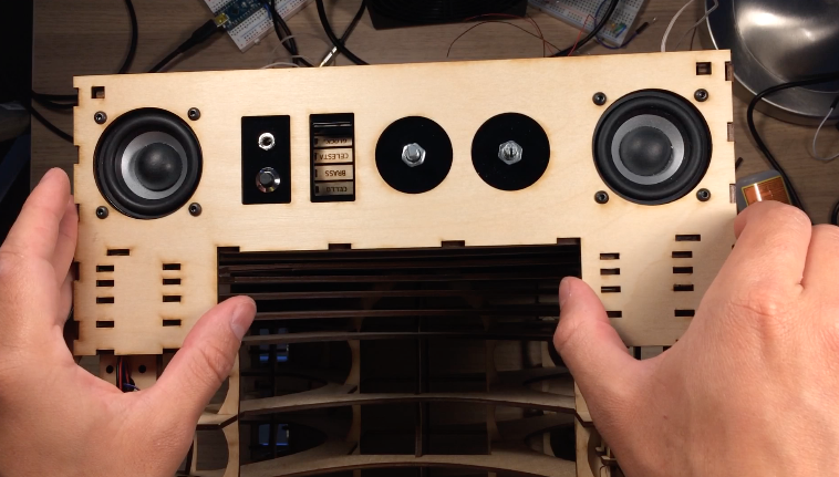
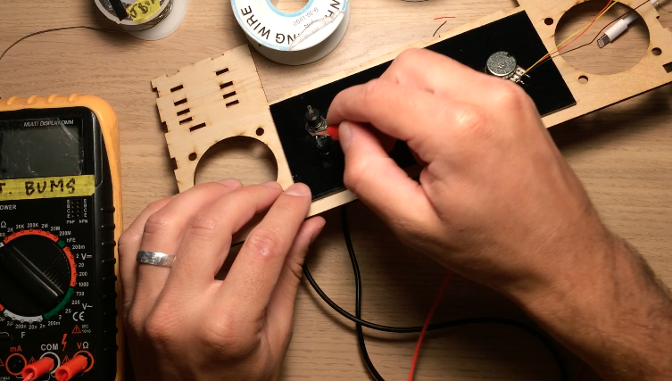
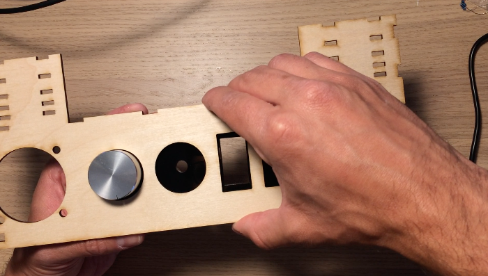
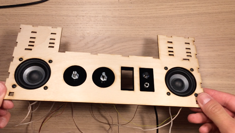
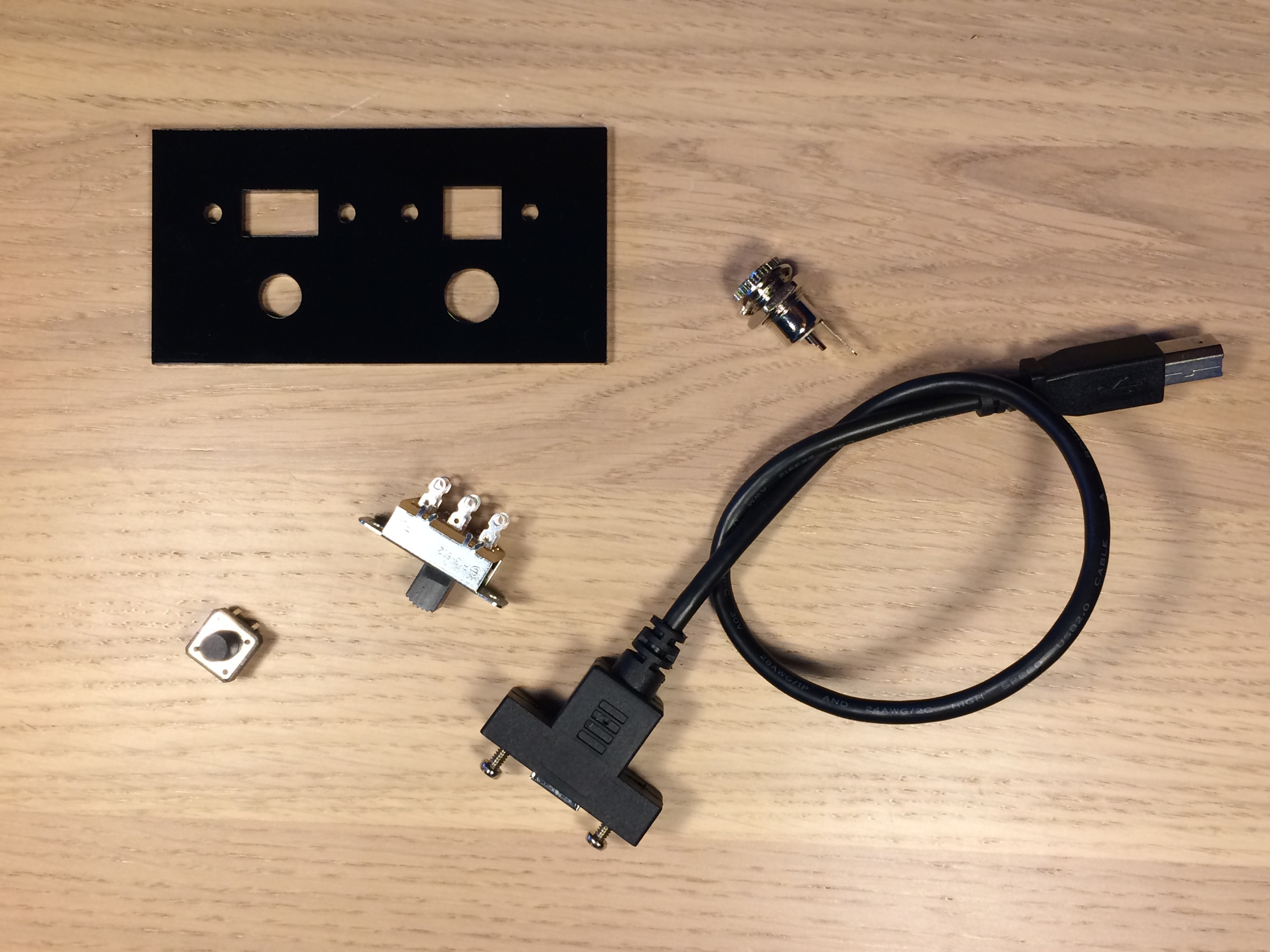
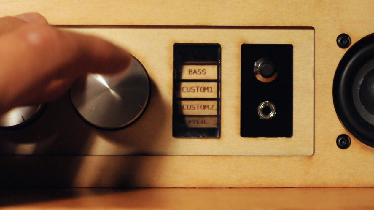
I decided to build the device with two separate panels. In the rear are the jacks and switches for power and uploading programs to the device. In the front are all the controls related to controlling the instrument and audio of the device.
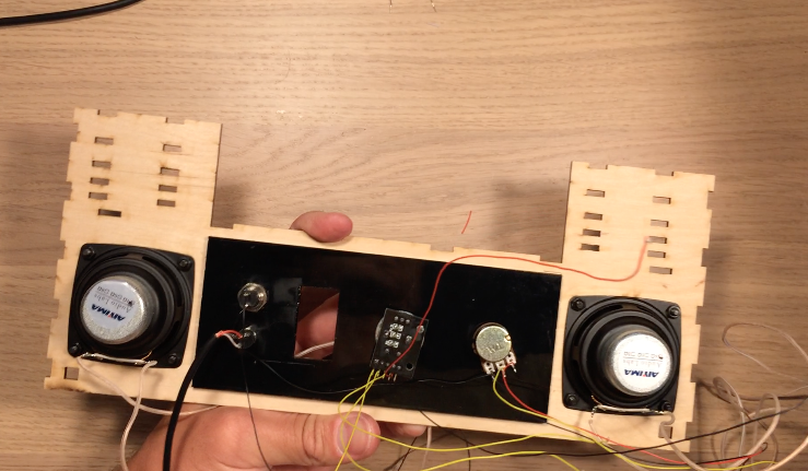
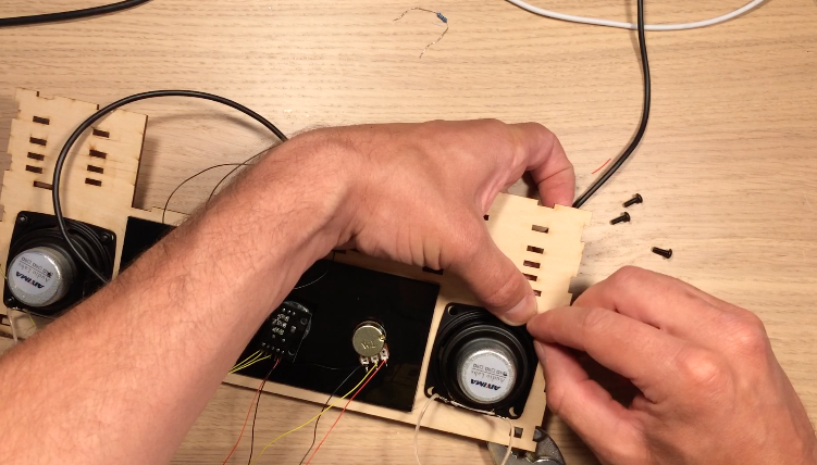
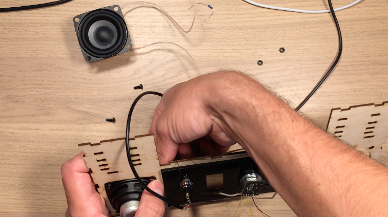
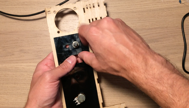
Black acrylic pieces hold the components on the rear and front panel. Both acrylic panels are glued onto the wooden front and rear walls of the electronics box. After gluing the acrylic, I mounted the potentiometer, rotary encoder, on/off speaker switch, and headphone jack. On the rear, I attached a reset pushbutton, on/off power switch, power jack, and USB jack for uploading programs to the Arduino.
The front and rear walls were then hammered into Layers 10-15, just like the side panels. At this point, I also connected the corner joints at the bottom of the device. A nut is glued into these joints so that bolts can hold on the bottom panel.
I did a lot of soldering and wire wrapping to connect all the components as shown in the schematic. The power supply is 12V, so I made sure the Buck converter was adjusted for 4.5V output before connecting lasers and the motor. Finally outer walls for the electronics box were glued on to cover the Layer 10-15 tabs.
![]()
![]()
![]()
![]()
![]()
![]()
![]()
![]()
![]()
![]()
![]()
-
13Playing the Harp
The code for the upright laser harp is uploaded in the Hackaday documents. I also included smaller bits of code for troubleshooting. I followed the code from the Adafruit documentation for the Music Maker shield. The general procedure is as follows:
SETUP
1. Calibrate the instrument wheel with Hall effect sensor signals
2. Set up Music Maker Shield for MIDI output
3. Select the notes played by the device
4. Turn lasers on
LOOP
5. Update volume of device by reading the potentiometer
6. Update the motor position and MIDI instrument by reading rotary encoder
7. Read the state of the photoresistors and compare to previous state to determine if beam was blocked
8. Send appropriate MIDI signal if beam is blocked
The Reset button and Speaker enable button work by being tied to ground so they don’t have to be read into digitial pins of Arduino. You may have to adjust the lasers using the kinematic mounts to make sure they are aligned with the photoresistors.
Upright Laser Harp
New spin on the laser blocking musical instrument


Discussions
Become a Hackaday.io Member
Create an account to leave a comment. Already have an account? Log In.