Jonathan Bumstead
-
Original project plans
09/12/2019 at 03:16 • 0 commentsAfter completing the first prototype, I turned back to my original handwritten project plans. Looking back on these plans is also helping me with the next steps in the project. In this project log, I wanted to go over a few design decisions I made early on in the project and how they affected the system development.
1. Laser beam trajectory
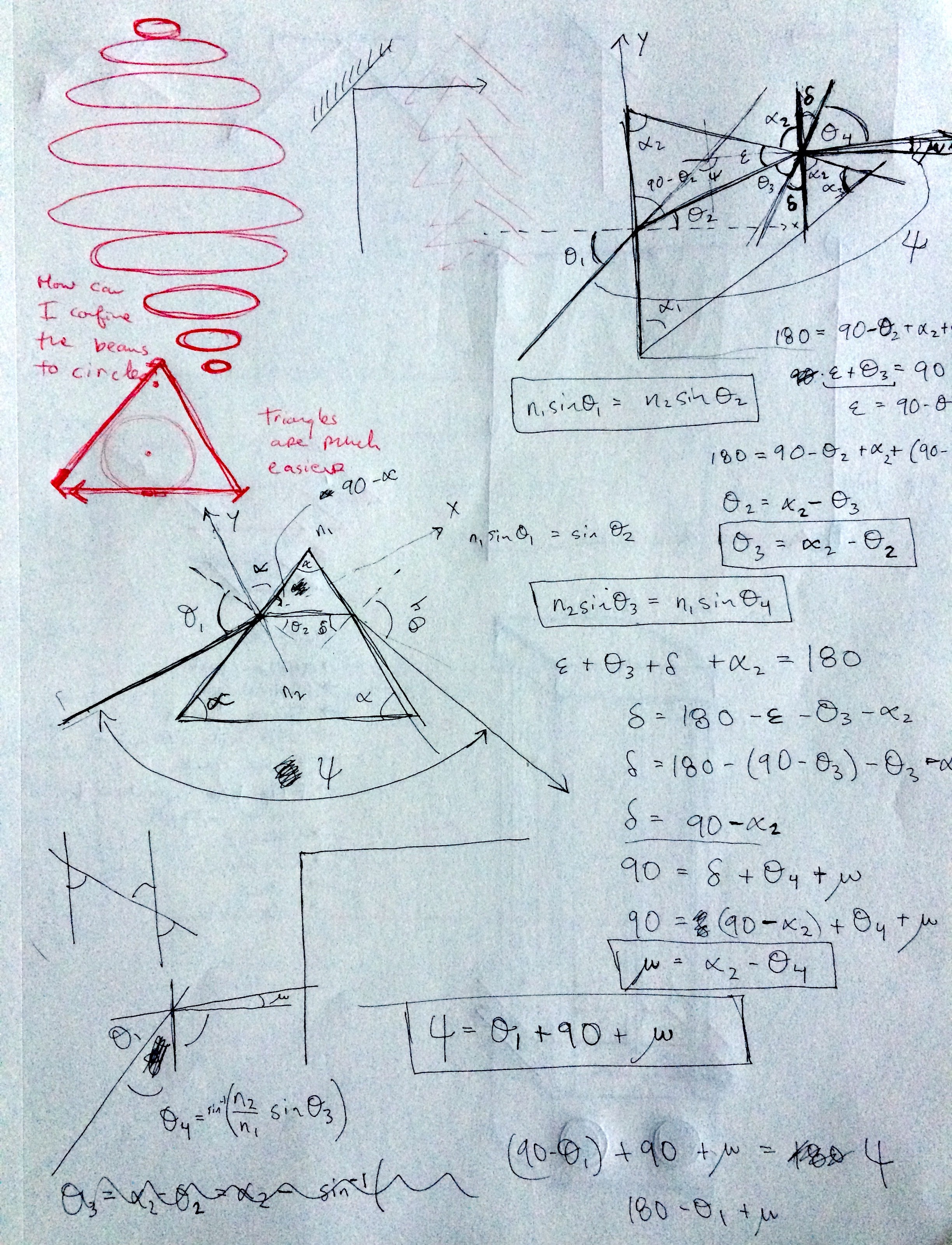
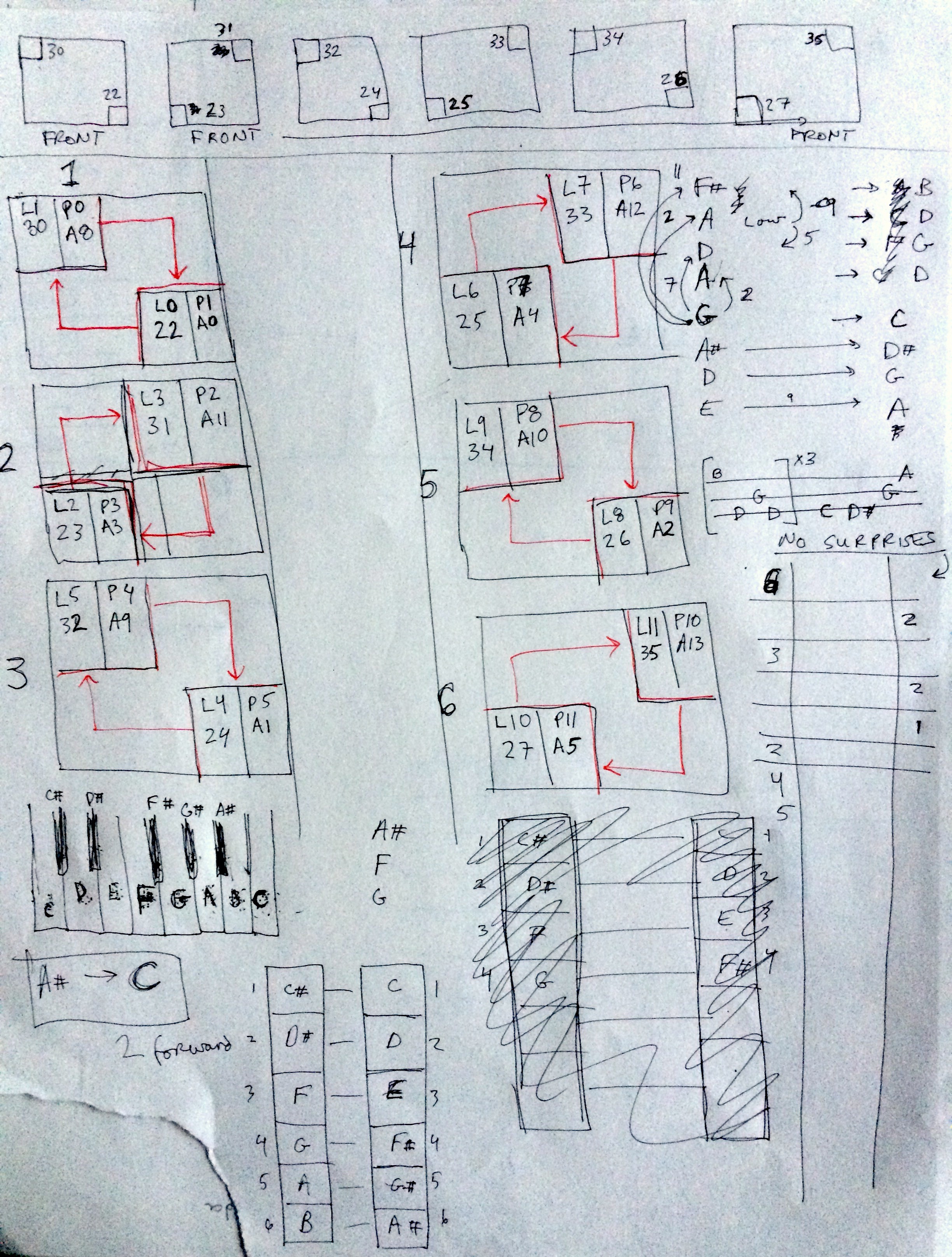
I knew from the beginning that I wanted the lasers to propagate horizontally in a closed loop, but I wasn't sure how to shape the closed laser loop. I originally thought the laser beam wrapping into a circle would be best. This idea was inspired by the laser vortex projects and my laser sheet generator musical instrument. However, I soon realized it is difficult to wrap a laser beam into a circle. The closest solution I could find was using many prisms, but it would be expensive and difficult for the user to break the beam because all the prisms are in the way. In the photocopied page you can see my plans for circular laser trajectories and math to figure out how to achieve them with prisms.
![]()
I eventually settled on making square trajectories because they were so much easier to construct. Initially I thought this was a setback in the development, but later thought square trajectories would look great and make the most sense to play.
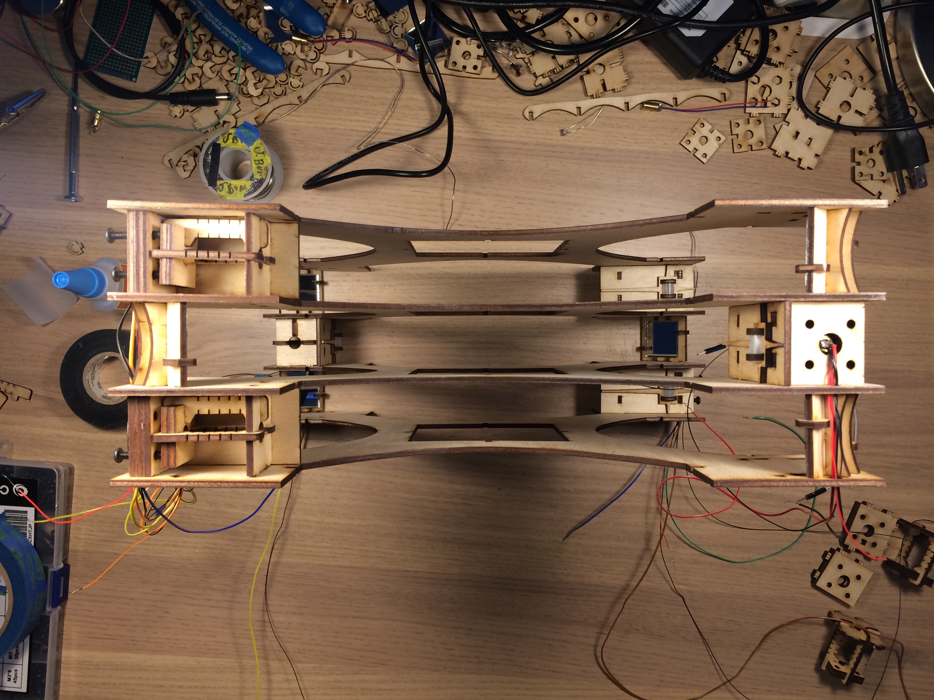
2. Tower height and layer spacing
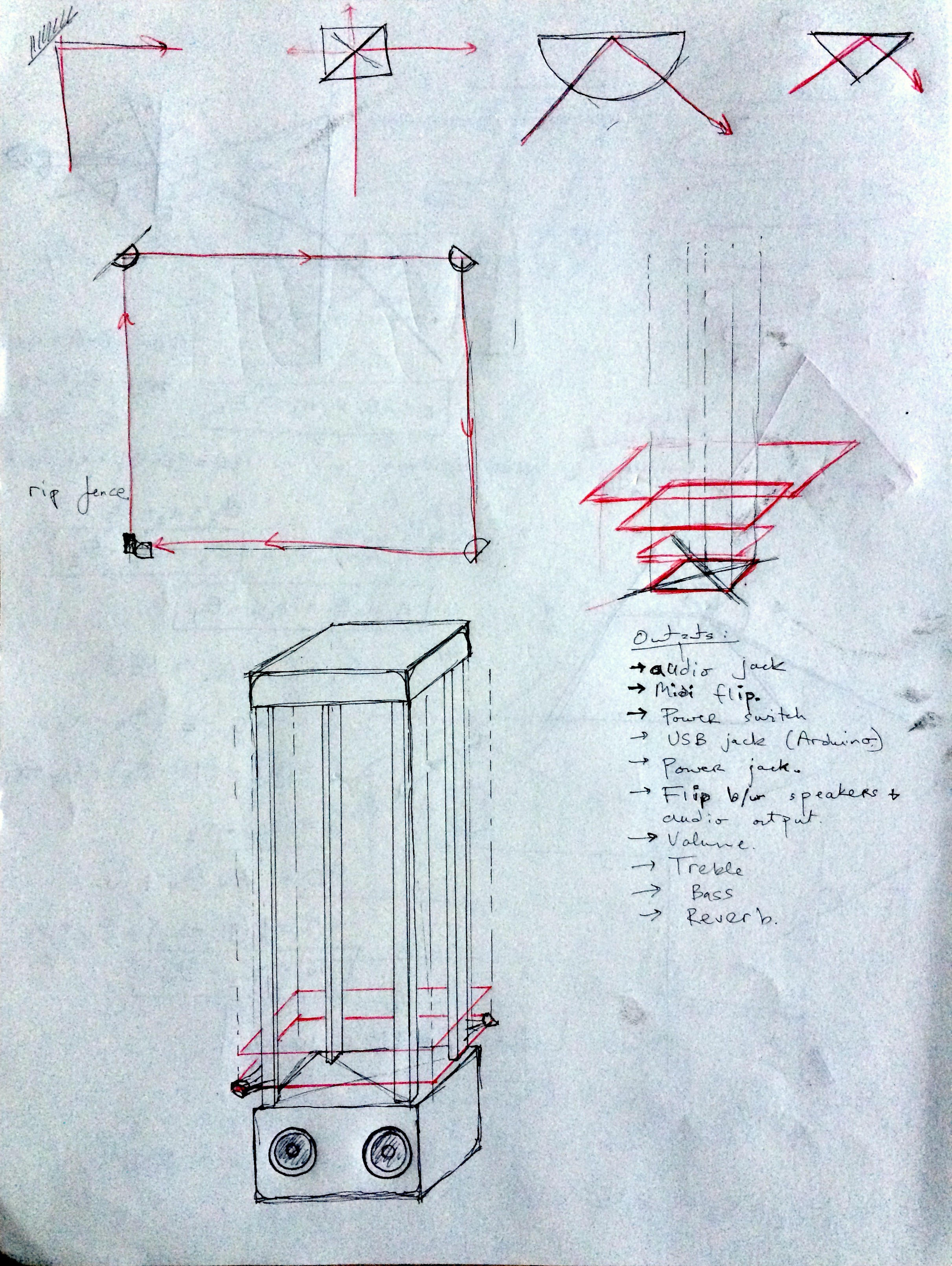
In my first sketches, I imagined the upright laser harp being really tall with one laser on each layer. From the drawing, it looks like I always knew there would be two small speakers on the front of the device.
![]()
After getting some feedback from my wife, I switched to a shorter design with two lasers per row. I liked the compact look more and I started to realize that a major advantage of this design in general is a smaller system that is easy to carry around.
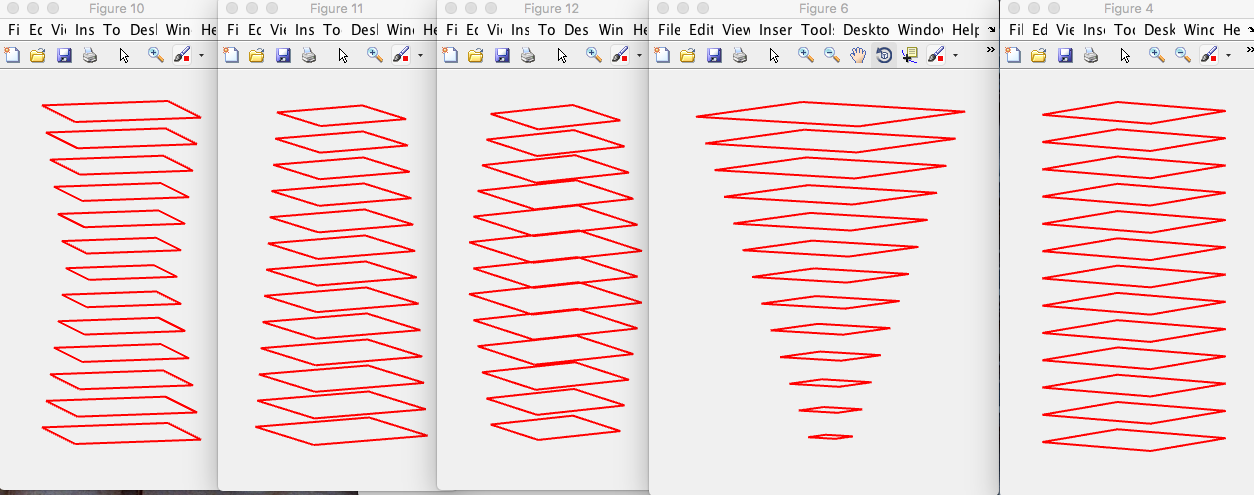
I also took some time modeling the stacked laser trajectories using Matlab. I needed to decide if the trajectories would change in the vertical direction.
![]()
Here you can see a few ideas I had. I liked the symmetry and simplicity of the constant trajectory size in the drawing to the right of the figure. This design would also be easier to construct and test the idea.
3. How to redirect the beams
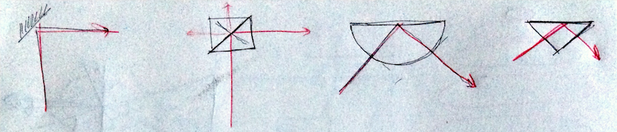
At the beginning of the project, I really wanted to redirect the light using prisms so that the laser beam would be visible throughout the entire trajectory. If I used mirrors, I worried that they would block the view of the beam path. After doing some math, I realized that a 90deg turn by refracting light through a prism would not be possible. However, prisms can redirect light in a 90deg turn through total internal reflection. I made an order for Hemicircle shaped plastic, which also can redirect the beam 90deg. I was disappointed how much of the laser light was still transmitted (so much for total internal reflection!). The losses were too much and the alignment was a nightmare. I decided to just go with small mirrors, which were cheaper and easier to work with.
![]()
To make up for this short coming, I made the device as "see-through" as possible so that it was easy to see as much of the beams as possible.
![]()
One last sketch here showing some of the planning for how to layout the lasers and how the beams should be tuned.
-
Mounting electronics and soldering
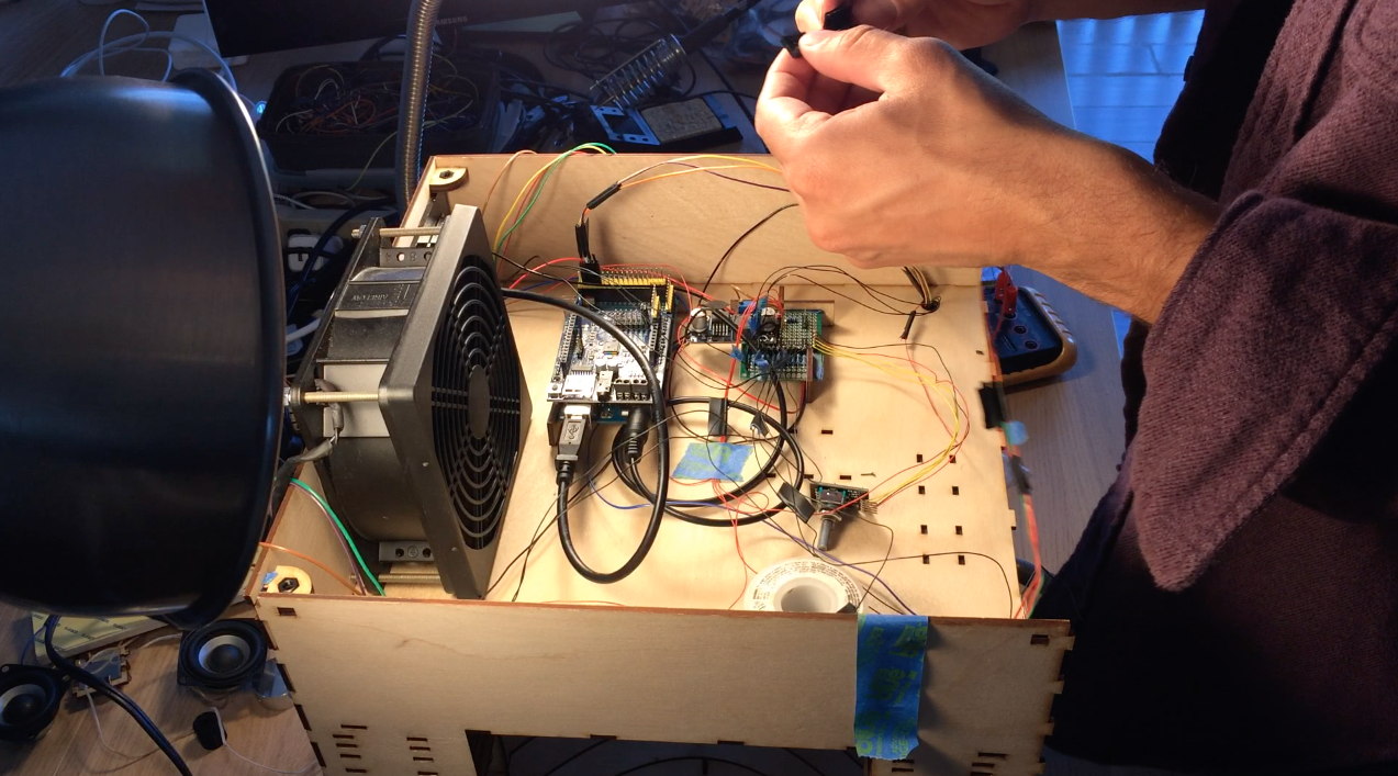
08/24/2019 at 01:38 • 0 commentsI designed all the electronics to be mounted to the top of the electronics box so that the bottom panel could easily be removed if the electronics needed to be troubleshooted. The Arduino Mega, stepper motor controller, prototype board, and instrument wheel are all pressed into the top of the box using the mounts. A few lasercut parts slide over the boards as shown in the images above. These parts then press into the holes in the top of the box.
![]()
![]()
![]()
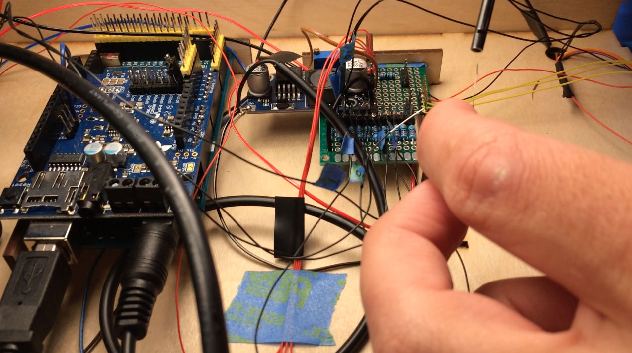
All the electrical components shown in the diagram are soldered to the prototype board: transistors for controlling the laser diode modules, resistors for the photoresistor circuit, pins for front panel components. There is a lot of soldering work here so I'd like to some day make a PCB for the upright laser harp.
![]()
-
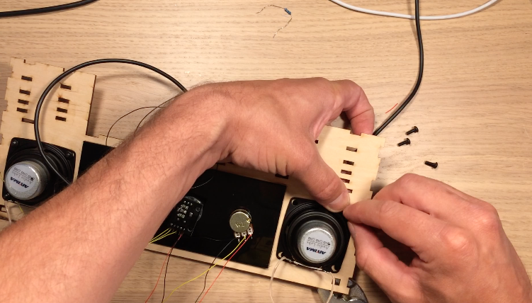
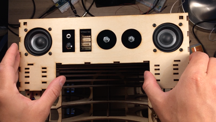
Front and rear panels
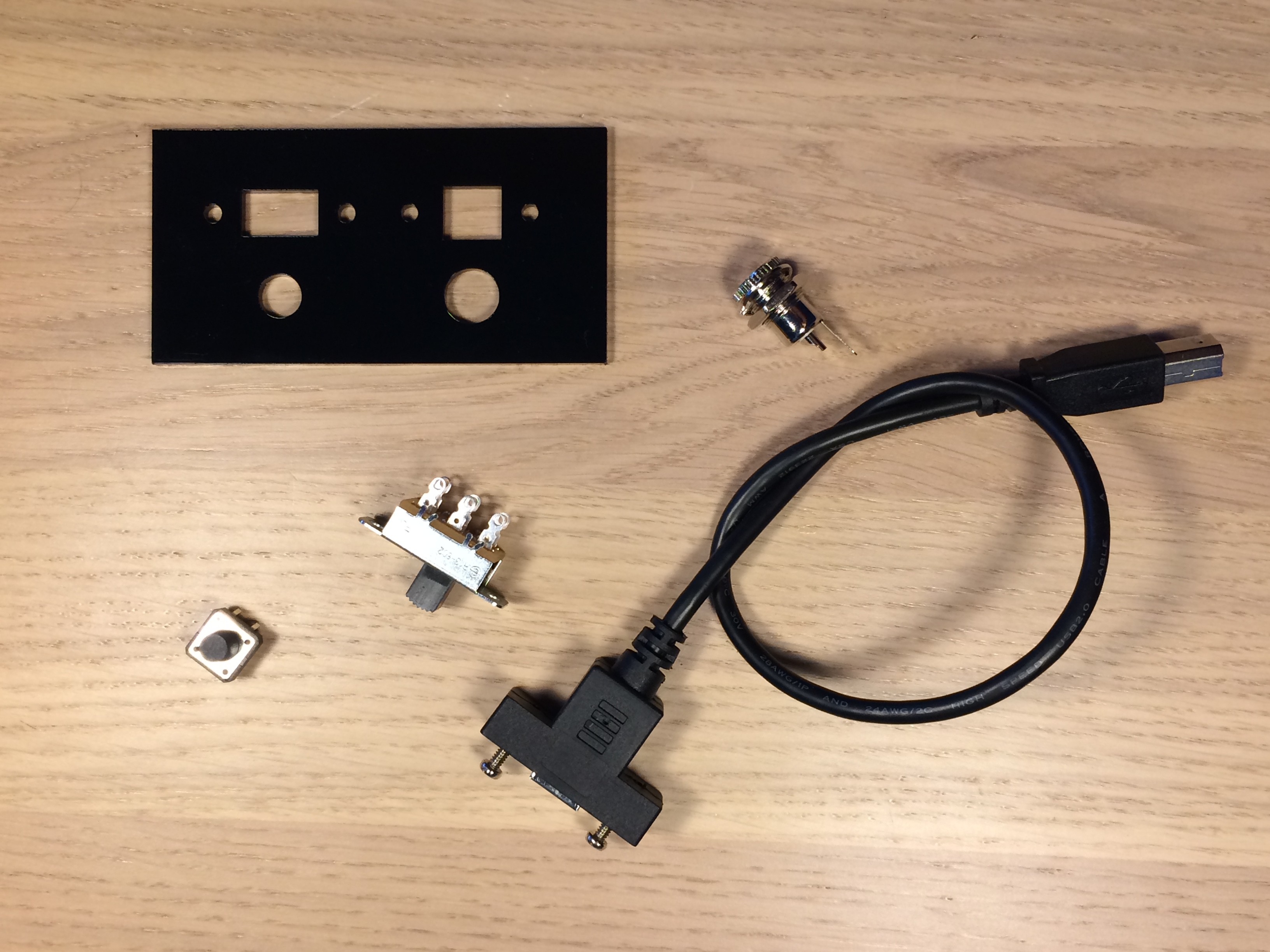
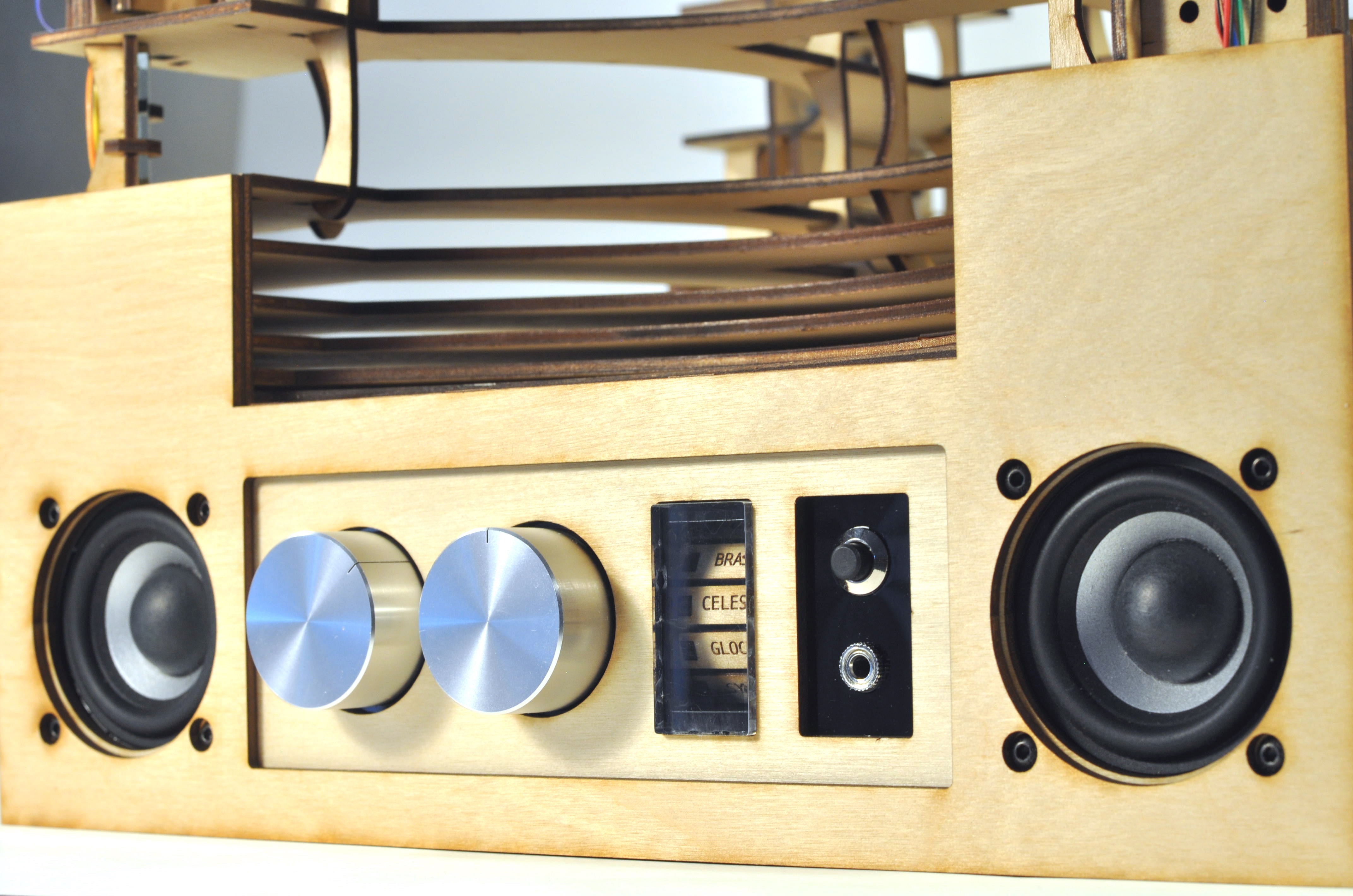
08/23/2019 at 04:42 • 0 commentsI decided to build the device with two separate panels. In the rear are the jacks and switches for power and uploading programs to the device. In the front are all the controls related to controlling the instrument and audio of the device.
![]()
Black acrylic pieces hold the components on the rear and front panel. Both acrylic panels are glued onto the wooden front and rear walls of the electronics box. After gluing the acrylic, I mounted the potentiometer, rotary encoder, on/off speaker switch, and headphone jack. On the rear, I attached a reset pushbutton, on/off power switch, power jack, and USB jack for uploading programs to the Arduino.
![]()
![]()
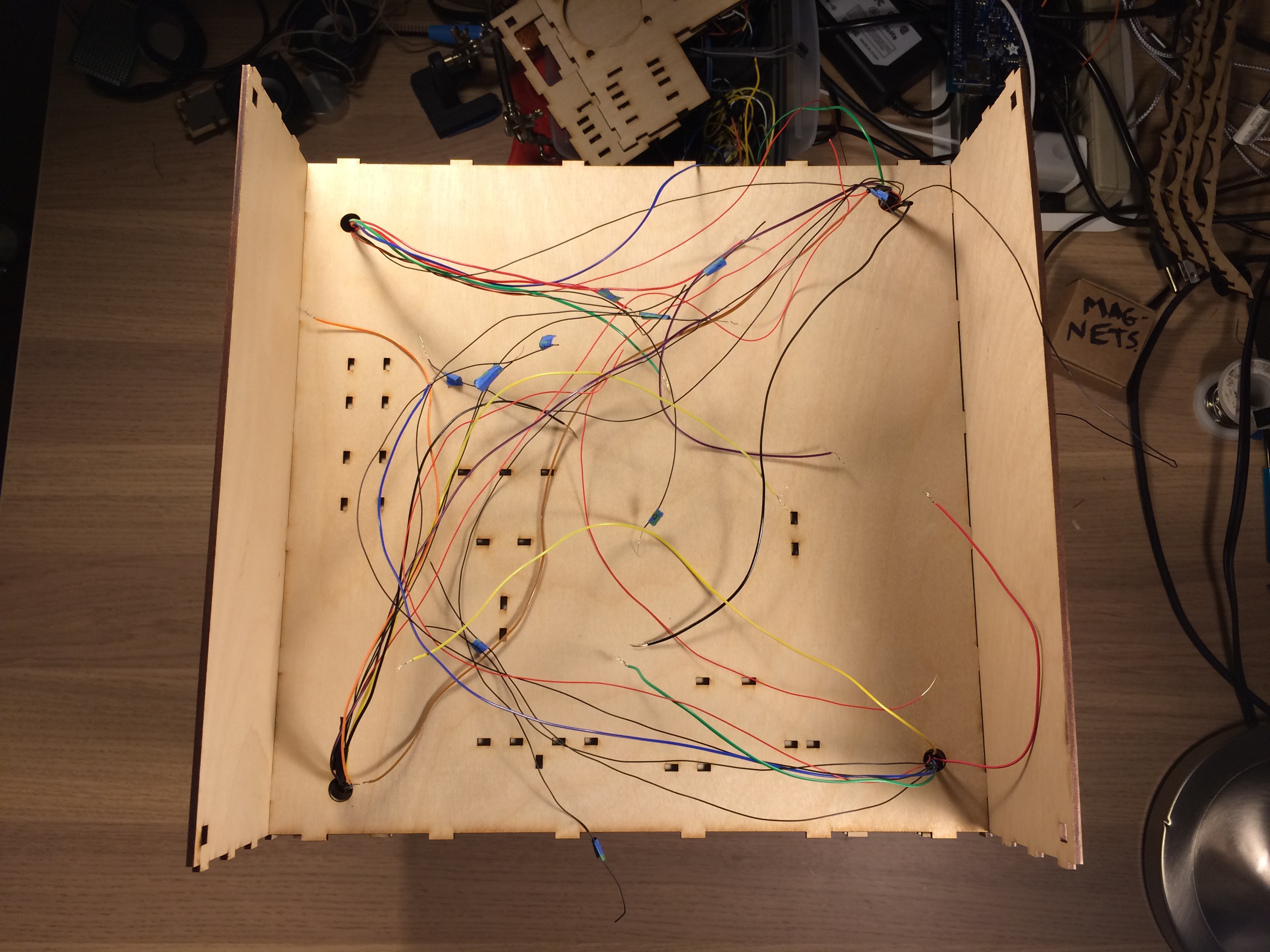
The front and rear walls were then hammered into Layers 10-15, just like the side panels. At this point, I also connected the corner joints at the bottom of the device. A nut is glued into these joints so that bolts can hold on the bottom panel.
![]()
I did a lot of soldering and wire wrapping to connect all the components as shown in the schematic. The power supply is 12V, so I made sure the Buck converter was adjusted for 4.5V output before connecting lasers and the motor. Finally, the outer wall for the electronics box were glued on to cover the Layer 10-15 tabs.
![]()
-
Instrument wheel
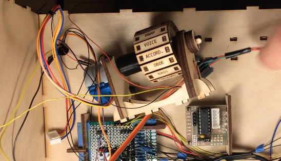
08/22/2019 at 02:29 • 0 commentsThe laser harp can cycle through MIDI instrument sounds. I chose to preload 16 instrument labels on the Arduino that would be sent to the VS1053 chip on the Adafruit music maker shield. The number of instruments is not limited by the Arduino and music shield. There are over 100 options for instruments on the VS1053 chip. I think there is probably enough memory on the mega to store all those instrument codes if you wanted.
![]()
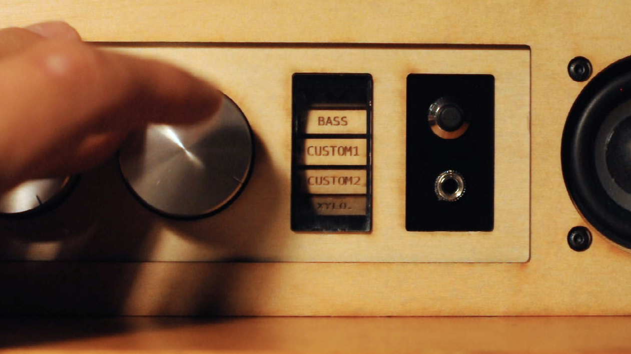
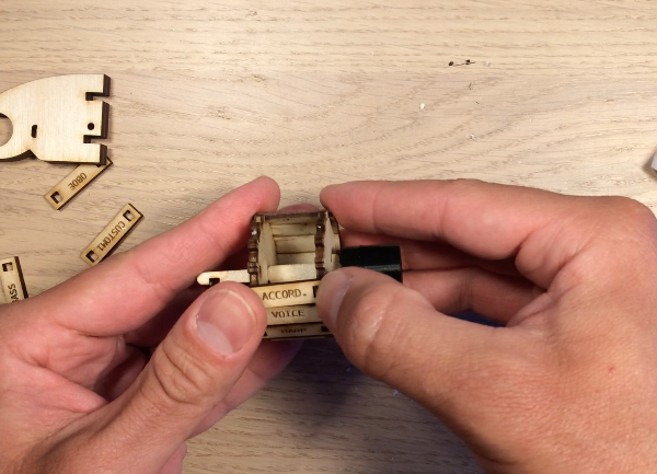
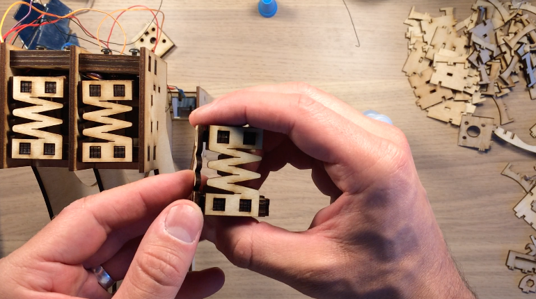
To display the selected instrument, I designed an instrument wheel that rotates. An instrument name is written on each plank on the rim of the wheel. The signal from the rotary encoder changes the instrument and rotates the motor so the user knows which instrument is being played.
![]()
The stepper motor is secured onto the mount with two bolts. There is directionality to this mount; see the CAD model gif and video to make sure everything is in the right direction. A 3D-printed motor coupler connects the motor shaft and wheel axle. The two axle pieces are glued together and pushed into the coupler. Then the first face of the wheel (the one with the bigger rectangular cutout) slides over the axle, followed by the second face of the wheel. Some wax may be required because it is a tight fit. The rim of the wheel with the instrument types holds the two faces together. The words will be upside down when viewing the wheel with the first face to the right of the second face.
![]()
Next the two parts holding the Hall effect sensor are glued together. The Hall effect sensor is used to determine the position of the wheel. The bipolar Hall effect sensor switches high to low when the magnet field over the sensor changes. Two magnets are therefore placed on the wheel facing opposite directions. The wheel rotates until the sensor reads high and then switches to low. Some offset in steps is then added to position the first instrument at the right position in the display.
![]()
The Hall effect sensor is pushed into place with housing over the middle lead to avoid a short. Check the wiring in the schematic. Now three circular parts slide over the axle so that the axle can turn in the circular hole in the Hall effect sensor mount. Two C-shaped parts are pushed orthogonally into the axle to hold everything in place.
![]()
The motor is then connected to the axle via the coupler, which holds a nut and set screw that presses into the motor shaft. Finally, the whole assembly is held together with two spline shaped mounts.
-
Photoresistor design
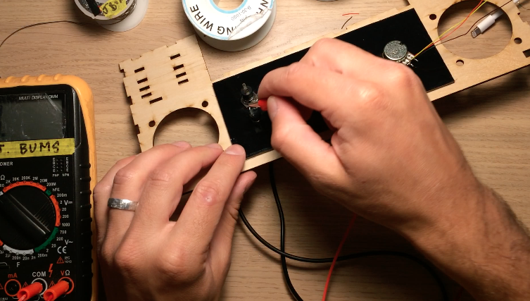
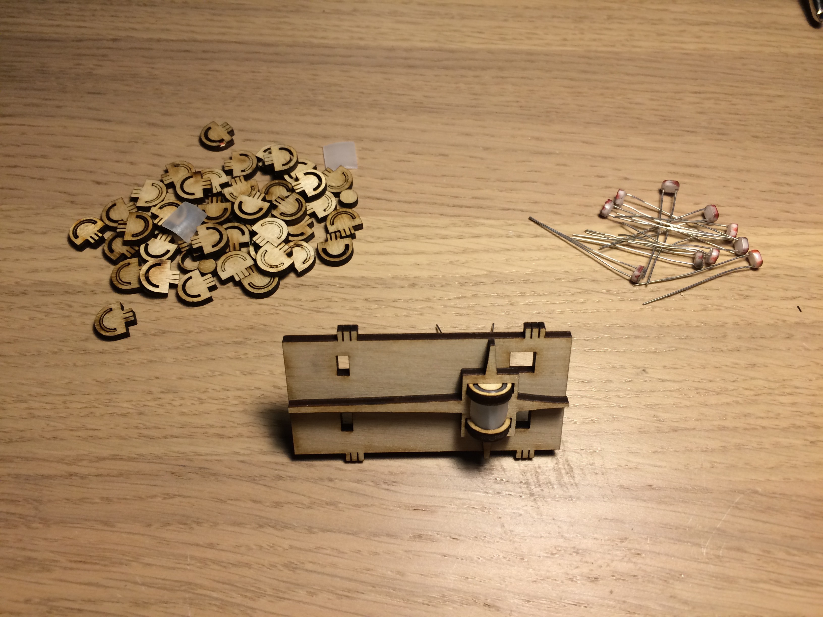
08/20/2019 at 05:02 • 0 commentsTo detect the blocked laser beam, I decided to use photoresistors. I debated using faster components, but, after watching this great Backyard Amusement video, realized that photoresistors would work fine given my requirements.
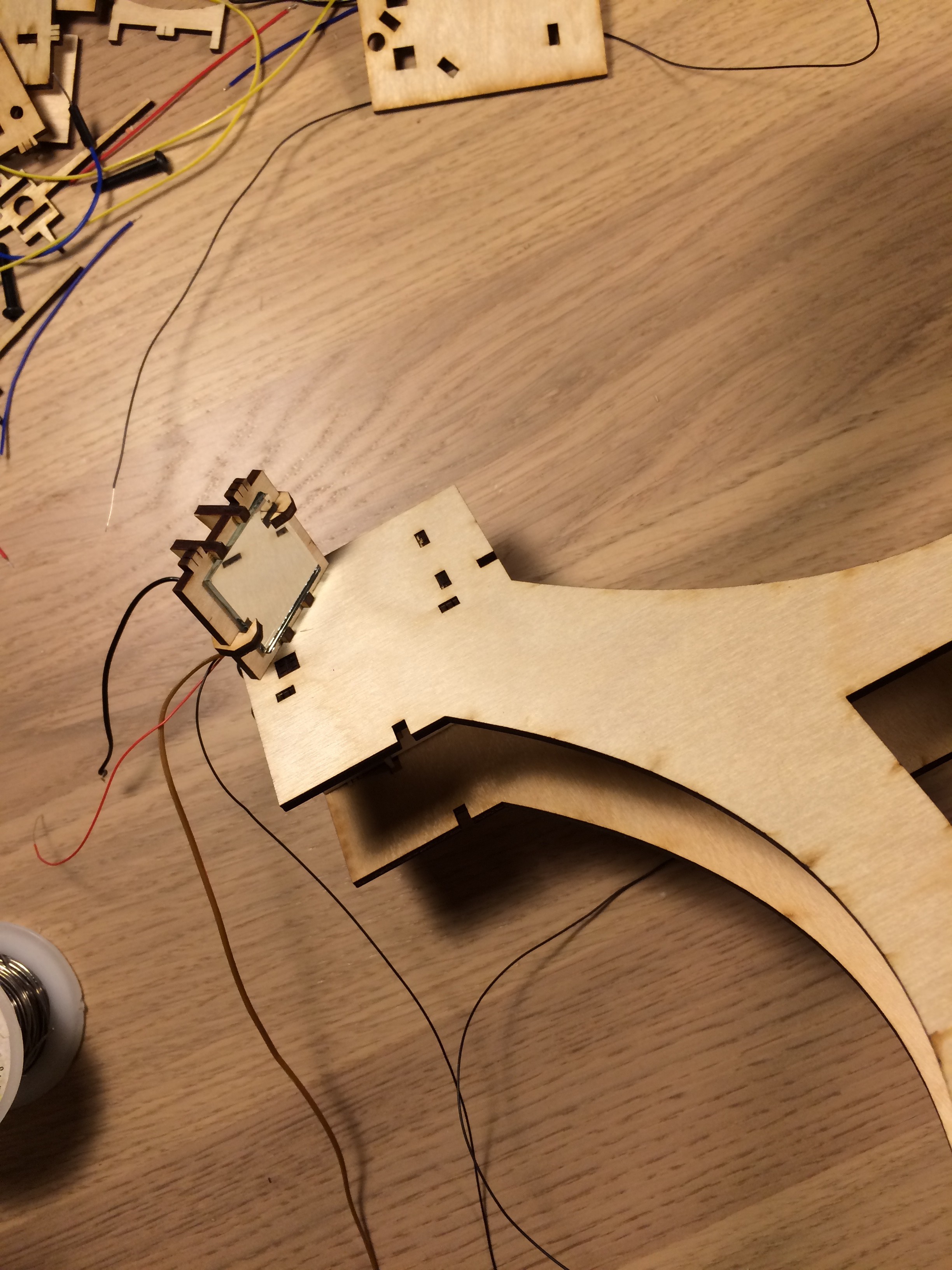
Even with the kinematic laser mounts, I knew that I wanted to add diffusers to make sure light fully illuminated the photoresistors. I used old 35mm film canisters cut to fit in a small mount, a trick I learned from my first laser harp.
![]()
A photoresistor is pushed into the photoresistor "wall," and two cables are connected to the photoresistor (one goes to 5V and the other goes to an analog input on the Arduino Mega). The film canister plastic slides into wooden mounts and is placed into a cross-shaped part. It looks like a little lantern. The body is pressed into the photoresistor wall. Finally, the photoresistor wall is used to connect the kinematic laser mount assembly. If the laser is aligned with the photoresistor, then a low signal out of the photoresistor corresponds to a blocked laser. The Arduino Mega is cued to play a note.
![]()
![]()
-
Mirror Mount Assembly
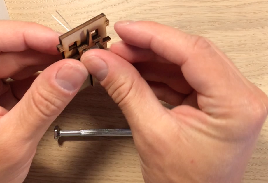
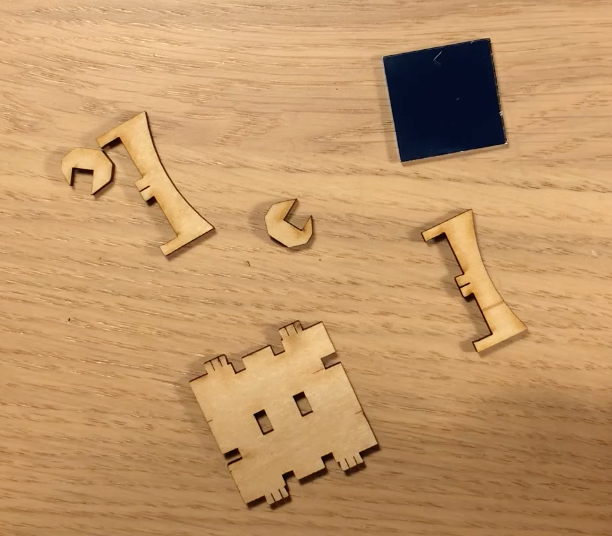
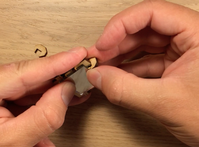
08/16/2019 at 04:18 • 0 commentsThe laser harp tower consists of twelve mirror assemblies and each assembly consists of five parts. Two brackets slide into the square mount and a 1" x 1" mirror snaps into place. To prevent the mirror from sliding out of the mount, two C-shaped joints slide in over the mirror. No glue is required for this assembly.
![]()
These 1" x 1" mirrors aren't the best quality, but they worked well enough for the single reflex between the laser and photoresistor.
![]()
![]()
![]()
-
Kinematic Laser Mounts
08/16/2019 at 03:43 • 0 commentsThe laser mount was the most difficult assembly to test and design. I wanted to be able to steer the laser for alignment with the photoresistors. In my previous laser harp, the lasers would get misaligned when I moved the device and there was no good way to finely adjust the lasers. Kinematic mounts are crucial components for optical systems, so I looked at existing devices for inspiration. All these devices use springs to apply adjustable force at specific locations in the device. My goal was to build kinematic mounts cheap, which meant replacing the metal springs with other materials. In my search, I also came across these LEGO-based kinematic mounts.
![]()
![]()
![]()
My first designs placed the mirrors on kinematic mounts with rubberbands. This worked pretty well, but the mounts were bulky and difficult to put together. I started to think of ways to make wood spring-like so I could avoid the springs and rubber bands. The final design consists of wooden arms with slits in them that made them flexible.
![]()
The mount consists of nine parts. First the rear body is put together with glue and four nuts placed inside. This part holds the screws that push the part holding the laser. Two parts holding the laser are glued together with the holes facing the screw. Finally, the three "spring" arms connect the front part and the part holding the laser. The laser is placed into the device later.
Upright Laser Harp
New spin on the laser blocking musical instrument