So at Roboys we have been using custom motorboards from the very beginning. The problem with those has always been the communication. We have a lot of motors to control in our humanoid. The influence of EMI is huge and SPI at high frequencies was a bad choice. The past is the past, and we need to move on. For our new motorboards we wanted something more reliable but also simple to connect. The simplest bi-directional communication setup is probably UART. You may think, wait but UART sucks in terms of baudrate. Well you are correct in the realms of micro controllers. If you take fpgas however, you are free to crank up the communication speed to very high frequencies. The only limiting factor is the wiring between your nodes. When it comes to EMI your best options are:
- shield your wires
- use differential signals
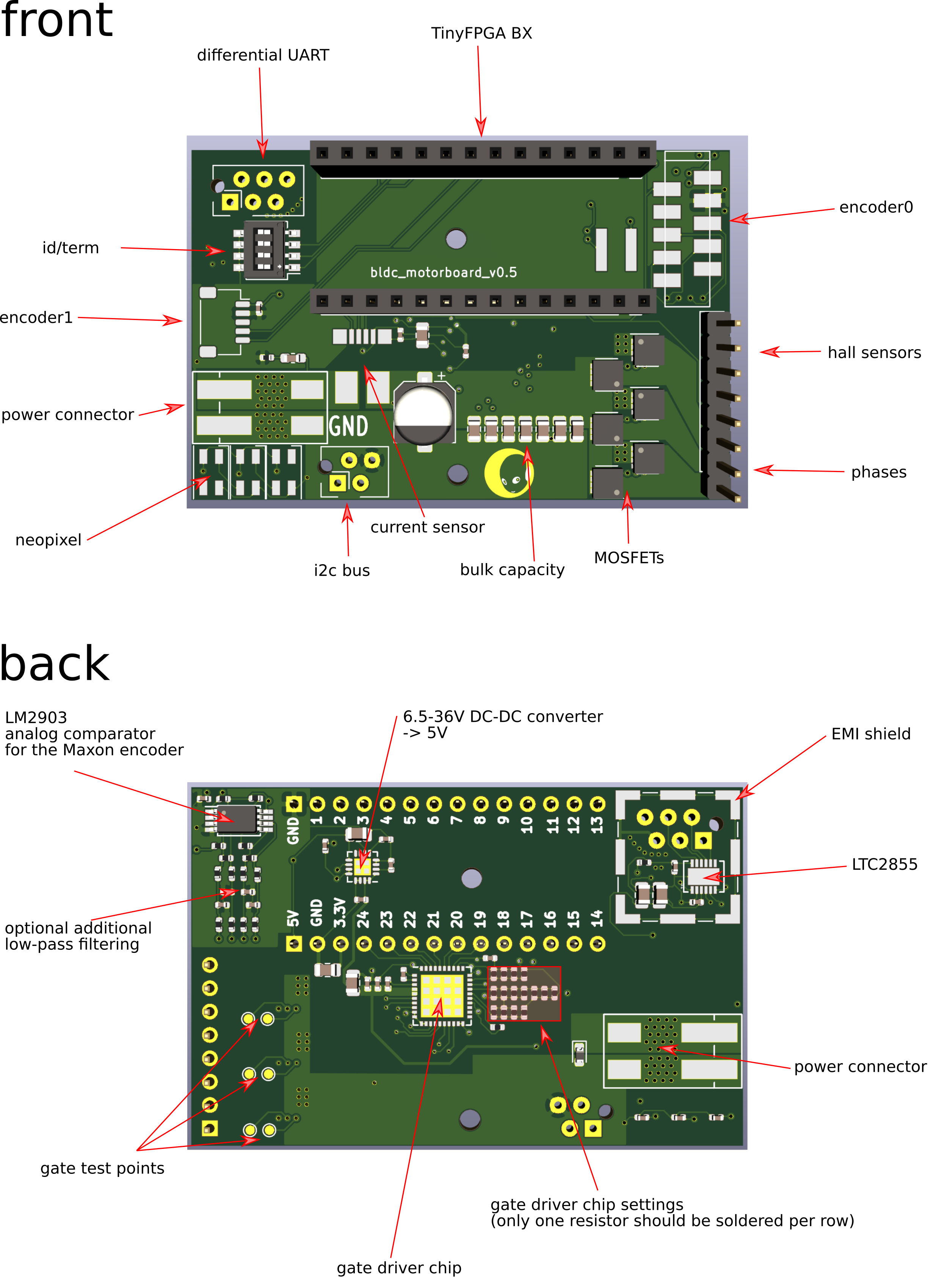
We decided on the LTC2855 from Linear Technology, because of its max throughput (20Mb/s) and the price. This chip integrates a driver and a receiver. It translates any outgoing signals to differential signals and any incoming differential signals are filtered to a single wire. Now, on long wires and high frequencies, you must often deal with unwanted echos of your signals from unterminated wire ends. This will pollute your transmission and you should always add termination resistors to compensate for this. The LTC2855 can add these resistors for you internally, all you need to do is pull one of its pins high for this.
The following illustrates all components of rev0.5:

For the UART communication we decided to write our own protocol, because it's fun. So here it is (oh BTW, this is totally preliminary and very likely to change in the future):

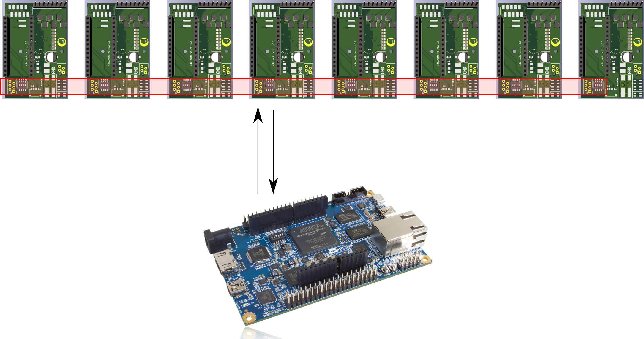
Our system architecture looks like this:

We call this the iCEbus (you get it?)
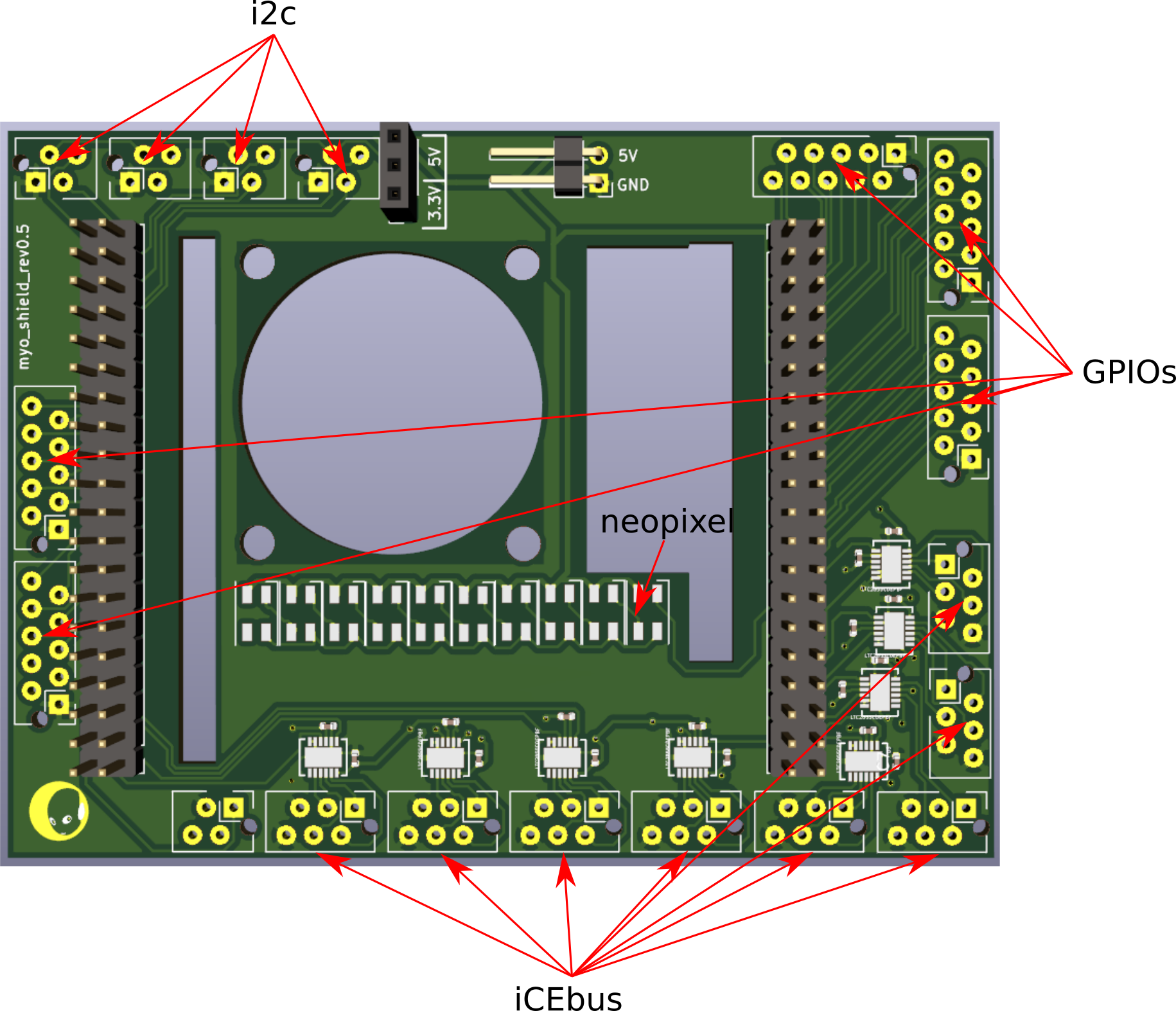
So the central node is our beloved de10-nano-soc, which integrates a dual arm core with 100k LEs FPGA. It's a dev-board from altera at about 110euro. We designed a shield for it featuring 8 LTC2855 to communicate with up to 8 motorboards per iCEbus:

So now I would like to talk a bit more about the iCEbus protocol. It works by a header mechanism in combination with a CRC16 checksum. All motorboards listen on the data transmitted from the de10. Each one shifts in bytes received with their UART modules (adapted from opencores). If a certain header is detected, the following data is received and after having received a certain amount of bytes (depending what header was received), the CRC16 checksum over the received data is evaluated and compared to the target CRC16 checksum (transmitted by the de10). If these sums match, and only then, the command will be processed. So far we implemented four message types:
- setpoint: header 0xBIGBOOBS (4 byte) motorID (1 byte) setpoint (4 byte) crc16 (2 byte)
- control mode: header 0xBAADAA55 (4 byte) motorID (1 byte) control mode (1 byte) crc16 (2 byte)
- status request: header 0xDABBAD00 (4 byte) motorID (1 byte) crc16 (2 byte)
- status response: header 0x1CEB00DA (4 byte) motorID (1 byte) position (4 byte) velocity (4 byte) displacement (4 byte) current (2 byte) crc16 (2 byte)
So the first two messages obviously control the setpoint and control mode of each motorboard. The third message requests a status update from the specified motorboard and the status response is the respective answer from the motorboard, obviously.
We were able to crank up the communication speed to 2MHz without any problems. This unlocks communication with each motorboard on an iCEbus with 500Hz (our target is 2kHz, but since ROS1 is not really able to handle more than 500Hz, we settled for the 2MHz for now). As I said, this protocol is very priliminary and is very likely to be augmented by different fields and messages in the future.
Control of the overall system is established via ROS. The de10 runs ubuntu 16.04 and exposes full control via custom ROS messages. These are processed in the arm cores of the de10, which then use Alteras AXI lightweight bridge to write the respective commands to the fpga. The communication with the motorboards is run completely transparent to the user. The de10 fpga code automatically checks if the setpoints and control_modes of each motorboard match what is wanted from them and triggers automatic messages if they dont match. Because all the message handling works in parallel on both sides, and because of the dedicated frame matcher mechanism the iCEbus protocol is preempt-able and hot plug-able.
 Simon Trendel
Discussions
Become a Hackaday.io Member
Create an account to leave a comment. Already have an account? Log In.