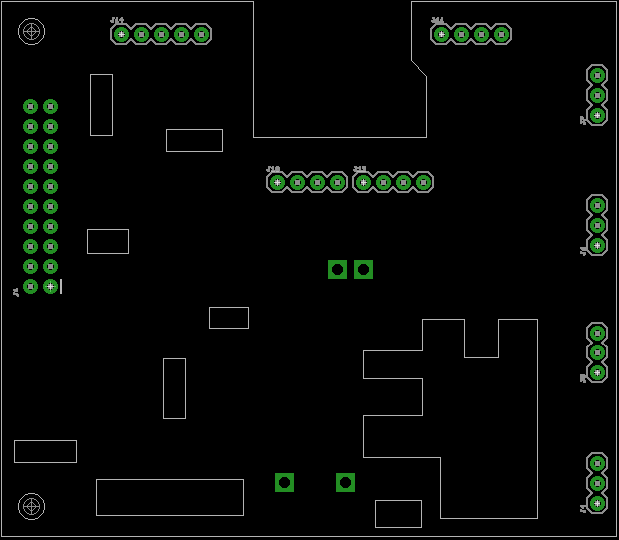
So you do a few measurements of the board and you get something like this:

The headers on there join up with the through hole parts that were standard 2.54mm pitch. The great thing about these is that there is one reference point in which to take the measurement from (pin 1). You could make the holes a bit bigger for these, to get around the solder joint, but in this instance the board doesn't have to be perfectly flush and I might just clean those joints up a bit before soldering anyway.
The other holes required were non standard pitch, so you can link these with vias. The via size just needs to be a bit bigger than the original solder joint/blob.
As for the rest of the solder joints, you can just route in cutouts where these are. These don't need to be too precise, just give enough clearance for the joints.
When using ImageJ, you can draw shapes around parts, then right click the yellow shape and click Draw, which leaves a white mark where you drew the shape. This is handy when using the measurement line. Also Ctrl+m is the shortcut for taking a measurement, which also shows instantly in the results window.
Also don't stress about the thin PCB section at the bottom, the PCB needs to grow about 10mm on the bottom edge to allow for a re-routing of the thermocouple headers, as the original ones have one pin shorted to ground (which isn't suitable for the thermocouple IC that's going to be used).
 Blecky
Discussions
Become a Hackaday.io Member
Create an account to leave a comment. Already have an account? Log In.