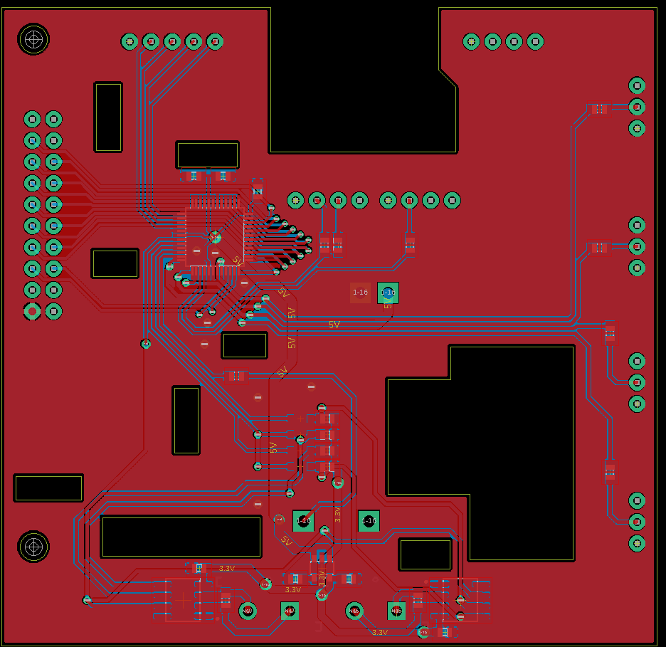
When placing components, note that the top layer of the board is the "bottom" of the main board, so we can put things anywhere on the top, and the bottom of our board will sit flush to the original board.
To get the thermocouples re-integrated, we have to add an additional section to the board. An additional board section near the existing thermocouple connectors has been extended to account for this. Here's a first cut:

Some notes about the existing board:
- LEDs are driven by the outputs, so there's no need to connect to these.
- Pullups are already on the buttons, so these aren't required again.
- There is a Dallas DS18B20 one wire through hole sensor which sits above the board. It is unknown what the actual purpose of this is, but I presume it is for cold junction compensation. But since it sits way above the board and is relatively far away from the thermocouple connectors, it's not really going to be accurate at all. If it is used as a generic temp sensor, then we can use the MAX31855 to get this instead and disregard the connection to it.
- There's a lot of other redundant connections, such as an unpopulated EEPROM connection.
 Blecky
Discussions
Become a Hackaday.io Member
Create an account to leave a comment. Already have an account? Log In.