 Blecky
Now to solder the board on. You want to join the existing leads to the new holes. This is made easier with a fine solder tip and feeding in the solder:
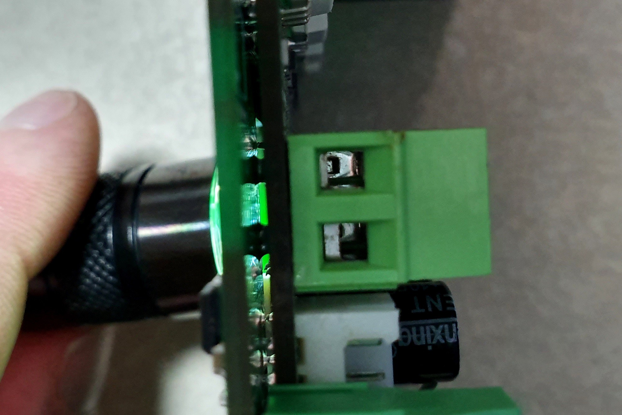
To check that pins have wetted, you can shine a light through the gaps in the PCB:
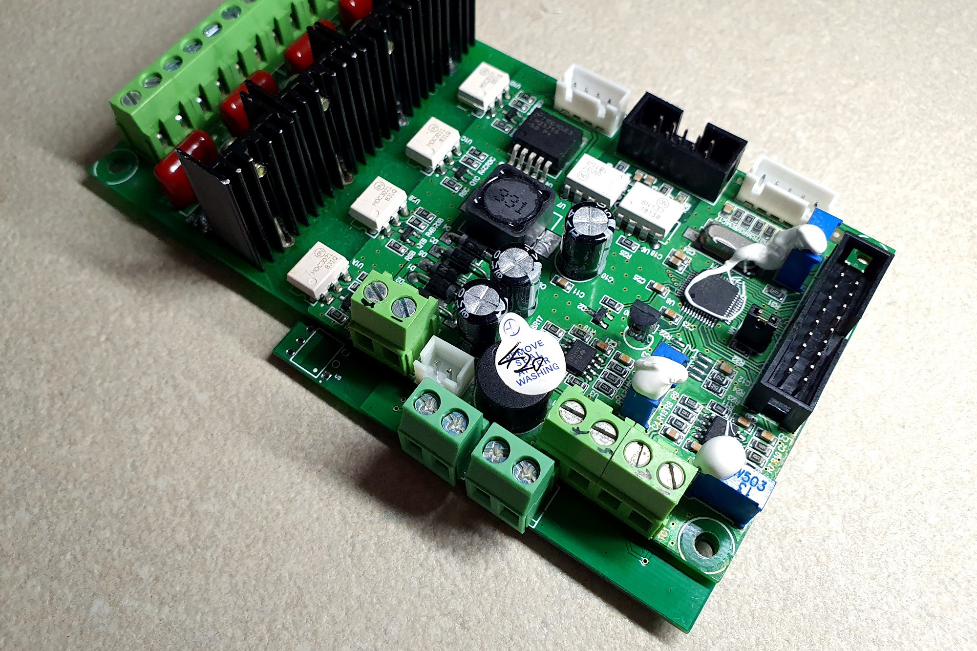
Et voilà:
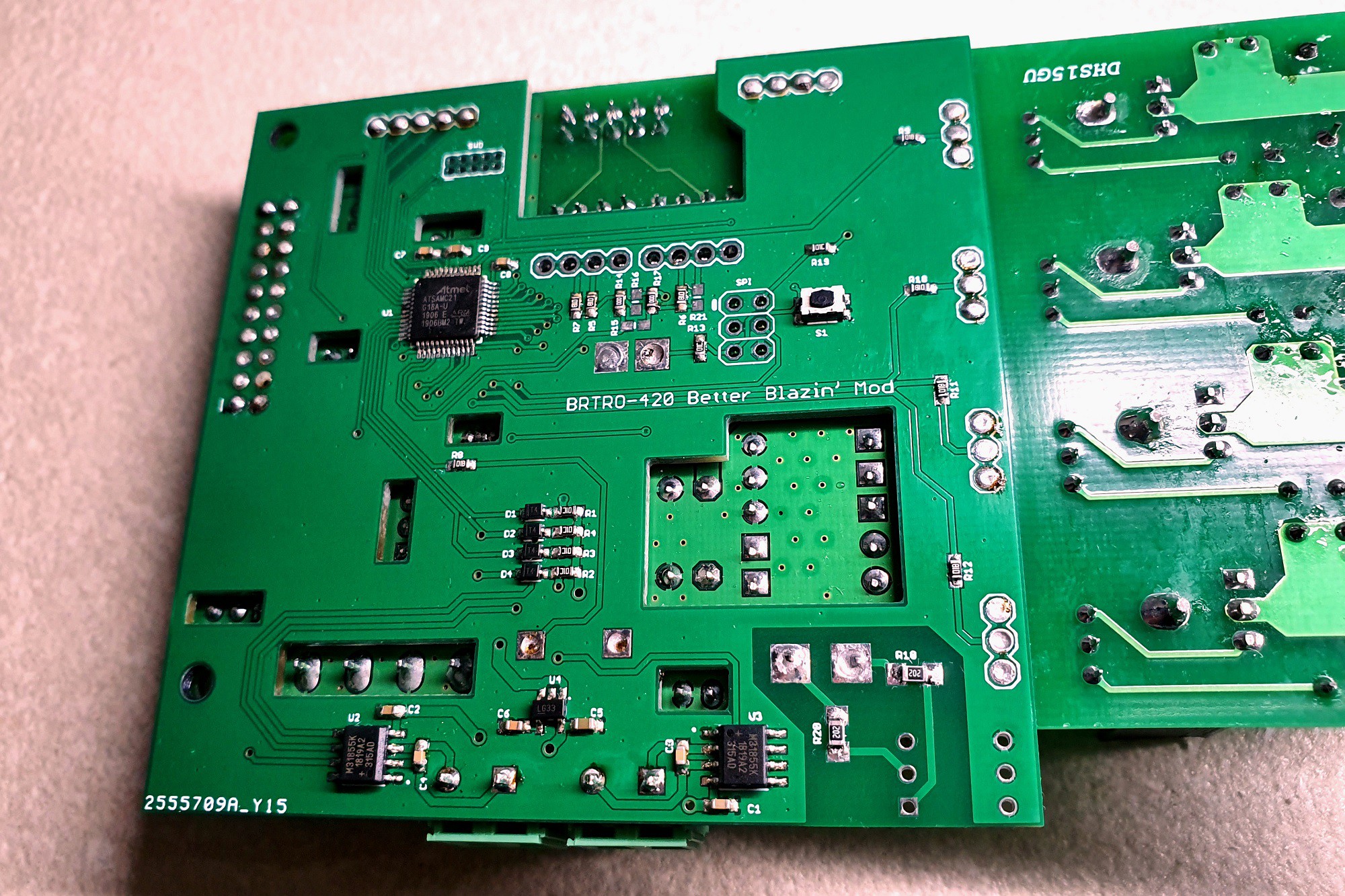
Also, pop a jumper on the W1 pins near the existing MCU (or bridge them with solder); this is the DEBUG I/F pin. This places this MCU into serial bootloader mode (MD = 0, DEBUG I/F = 0) and effectively renders it inoperable.
New 5mm headers have been placed for the thermocouples. You could reuse the existing ones if you prefer.
Discussions
Become a Hackaday.io Member
Create an account to leave a comment. Already have an account? Log In.