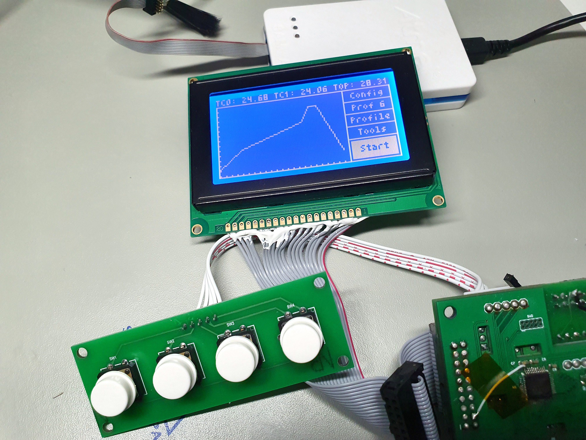
After ironing out a couple of PCB bugs, things are getting there. A trace got missed on the LCD display and the LEDs won't light up with the current rev of the board without a simple mod. But everything works now without any modifications required to the existing board (apart from putting a jumper on).
One of the buttons (back button) also managed to share the same EXTINT[3] with the zero crossing detection circuit on the SAMC21, so the button is handled separately in the main loop instead (which can cause a missed click every now and then, but it's not that bad).
It also turns out that the original circuitry and power supply was very very noisy, which causes random button presses and other minor undesirable issues like LCD glitches when not redrawing often. The new thermocouples are on their own 3.3V linear regulator, so there isn't much of an issue there. The buttons were fixed by having longer debouncing delays. This goes to show that the original hardware was completely inadequate for the task and the controller should really be replaced from the get go.
Most of the menu functions and profile modification/display features have also been created:

Now just onto the PID control and timing!
 Blecky
Discussions
Become a Hackaday.io Member
Create an account to leave a comment. Already have an account? Log In.