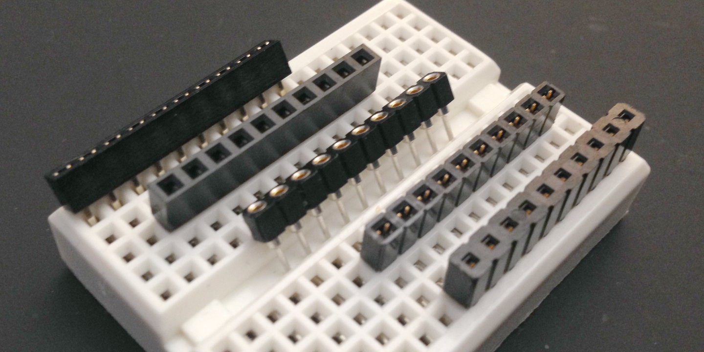
Attempting to make the whole package thinner, I went looking for shorter female pin headers than the 8 mm ones I had used. At western distributors, I found four manufacturers with suitable products: Samtec, 3M, PRECI-DIP, and Mill-Max. Three of them offered free samples, so I ordered some. With mixed success: One didn’t react to my inquiry at all. One sent me two pieces of the same part instead of the two different ones I had ordered. And one wrote the wrong country on the package and sent it on an odyssey around the world until it finally made it to me. In addition, I found one AliExpress seller, “E-Simpo”, who had two promising parts. They didn’t offer samples, but their 100-piece bags were affordable enough to risk an order.
So I ended up with 5 different samples to test, ranging in height from 3.5 mm to 5.0 mm. They all worked well mechanically with the 0.63 mm square pins of the male header. All but one were 2.54 mm wide, some with grooves between the pins, which would be an advantage, because that’s where my matrix pins lie. At 3.05 mm width, the Samtec CES-110-01-L-S was the first to be eliminated, because it covered more than half of the matrix holes, despite grooves. The remaining four were compared not only by height, but also by the insertion depth of the pin, because I wanted to leave as long pins as possible on the TinyPICO to keep it breadboard-friendly and compatible with other shields, rather than locking it in to the PicoPew. Champion in that regard was the E-Simpo 5 mm, which lets the pin go all the way through. Incidentally, it looks almost exactly the same as the ones sold by Adafruit in their “Short Feather Header Kit”.
| groove | height (mm) | insertion depth (mm) | |
|---|---|---|---|
| Samtec SLW-110-01-F-S | y | 4.5 | 2.9 |
| Mill-Max 801-47-010-002000/012000 | y | 4.2 | 3.9 |
| E-Simpo 5mm | n | 5.0 | 5.0 |
| E-Simpo 3.5mm | n | 3.5 | 2.7 |
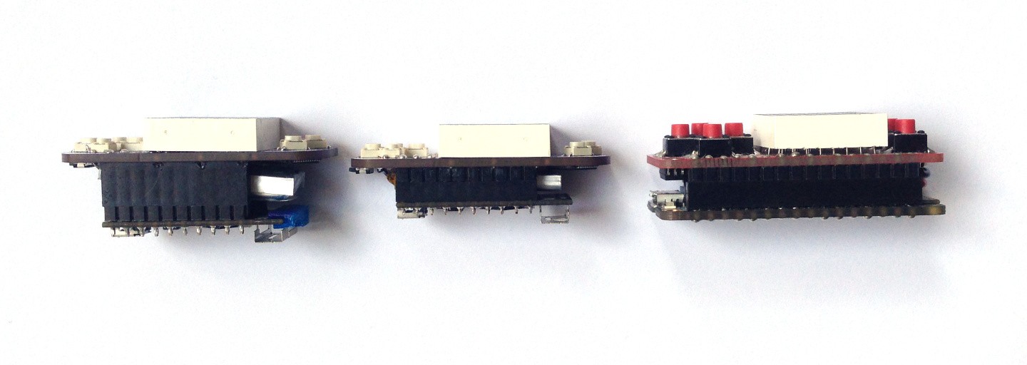
To fit a battery between the two boards, I need a gap of about 5.5–6 mm between the board surfaces. This could be achieved either by a 3.5 mm female header and the 2.5 mm plastic part of the male header, or by any of the three larger female headers and a gap, with the plastic part of the male header on the outside of the TinyPICO. The former case would definitely not be breadboard-friendly though, with only 2.7 mm pins remaining, and the latter, even with the longest pins afforded by the 5 mm header, only barely worked with the breadboards I tried.
Alternatively, I could mount the TinyPICO upside-down, with the components facing inward. That would require me to redesign the PicoPew board layout, but it would have the advantage of a nicer outer surface, with only the PSRAM chip sticking out. However, that wouldn’t be the usual way a TinyPICO is mounted on a breadboard or on another shield, and, more importantly, it turned out that to make space for the battery between the antenna and the USB plug, the whole thing would have to be made very thick again. With the plastic part of the male header on the outside, an 8 mm female header would be needed, and while the maximum thickness would actually be about the same, it would make the whole thing look much thicker. With the plastic part of the male header on the inside, a 5 mm female header would suffice. In both cases, the TinyPICO would just barely remain breadboard-friendly again, due to the space taken by the antenna.
With none of the options totally appealing, I decided to go with the first solution for now, but with the headers swapped: By putting the female 3.5 mm header on the TinyPICO, I could make it breadboard-friendly by inserting the short end of a male header – at the expense of some height, but that shouldn’t usually matter on a breadboard.
I assembled a second one of the three r1 boards that way and ended up with a perfectly working, nice and thin second PicoPew. The total thickness is about 0.5 mm thinner than a Feather board with a PewPew Lite now, but it looks thinner because it’s only the antenna sticking out that much.

This time, I also tried reflow soldering the components on the bottom of the board using a DIY oven built by a FabLab colleague, which worked well. Being extra careful around the header and matrix pins made that hand-soldering part less troublesome than the first time around too.
 Christian Walther
Discussions
Become a Hackaday.io Member
Create an account to leave a comment. Already have an account? Log In.
@Christian Walther forgot to tag you in my question.
Are you sure? yes | no
I have the feather low profile headers. I notice the pins stick out the bottom a little. I'm wondering, when I solder the headers, with the pins be able to stick out? Is there space normally in the hole for the pins? Or will it not sit flush with the header?
Are you sure? yes | no
Is there such a thing as low profile stackable headers? I've looked and can't find them anywhere. I basically want to duplicate what you can do with an Arduino and shields, but with smaller headers. Ideally, I would like to find a way to stack the round machine pin headers, but other than that, the square breakable ones are nice. I think the secret is you have to find headers with extra long pins out the bottom. I can stack two boards together with any header, but I need to stack three (or 4 depending how you look at it). I need a motherboard, then an ESP8266 type board on that, then a breakout board on top of that. The breakout board needs to also have a female header on it, but instead of plugging another board on that, I need the header to connect jumpers and leds. The top board is a test board that can be pulled off when done.
Are you sure? yes | no
I don’t specifically recall any with long pins, but I wasn’t looking for them. Samtec and Mill-Max have quite extensive catalogs though, have you examined those?
Are you sure? yes | no
I did. Let me just call them. Thanks!
Are you sure? yes | no
Thanks for the research, that will certainly come in handy!
I think that flipping the TinyPico would feel more natural if it had female headers on it — it's more standard to have female headers on top. But as you say, then you get into problems with the antenna and the USB socket colliding with the battery. Plus, the antenna might not work that well then.
Are you sure? yes | no
Let me know if you want any header samples.
It’s certainly standard on larger boards that don’t fit on a breadboard as well. Maybe I’ll do that redesign some day and see which way I like better. Maybe there are shorter batteries that would fit better.
Are you sure? yes | no