RGB LCD Backpack Addon
Additional IIC backpack for the IIC LCD backpack
Additional IIC backpack for the IIC LCD backpack
To make the experience fit your profile, pick a username and tell us what interests you.
We found and based on your interests.
LCD_RGB_Backlight_BackpackV0.2.inoVersion 0.2 - updated instruction setino - 4.23 kB - 09/07/2019 at 08:59 |
|
|
LCD_RGB_Backlight_Backpack.inoinitial version V0.1ino - 1.74 kB - 09/01/2019 at 15:15 |
|
|
RGB LCD Backpack Circuit.zipx-zip-compressed - 31.14 kB - 09/01/2019 at 07:42 |
|
Complete video of the test program I am using to make sure the device doesn't lock up. Ran for over 24hrs with no issues.
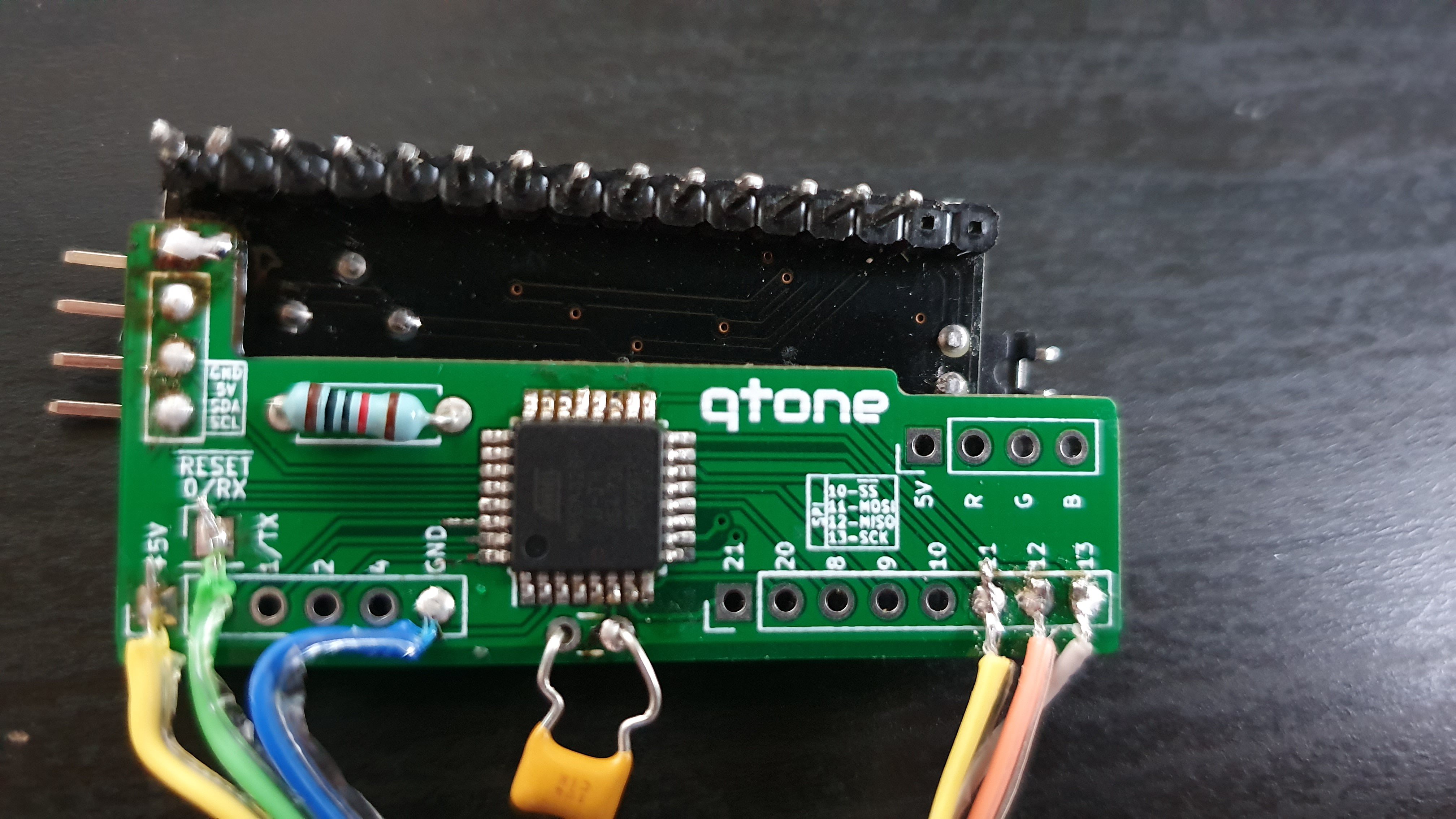
The prototype PCBs turned up this week and I have been having fun getting then working. I am still reasonably new to soldering SMT but flux is my friend! Even so, I was still having problems reprogramming the ATMEGA on my board. Turned out there was a minuscule solder jump between the SPI clock pin and the adjacent pin on the chip. Once I had that clear the chip took on the firmware with no issues.

There are some changes I would like to do to the PCB. As mentioned in the image above I've had to wedge the boards apart to make the LCD backpack work. I de-soldered the connector to allow my backpack to attach, but I don't think the solder has flown back down fully. Next version I will use larger holes so the connector can stay soldered.
Also my backpack doesn't lay flat as I have used through hole parts for the resistor and capacitor. The resistor is the issue as it obviously comes through. I have two thoughts on this. The obvious is to go over to surface mount components. The second is to solder the top side so the excess legs can be cut flush.
To finish off this log; another video demo!
While waiting for the PCBs to arrive I have been refining the firmware more. It is now possible to set the Hue, Saturation and Brightness separately in single byte commands. The 3 byte RGB command has been augmented with additional commands to set each colour separately.
There is also now an 8-bit RGB command which enables selection of 255 colours from a single byte (well 255 colours plus black). It uses the format BBGGGRRR. So red and green both have 8 possible combinations and blue has 4 giving the full 256 options. Below is the new command set and what colours are available with the 8-bit palette (please note the colours on screen WILL display differently compared to the LED output!)
I have added the current firmware for the backpack. It uses the FastLED library to enable some features. Due to a small mistake on my PCB design I forgot to add in the solder jumpers to enable the device to change it's IIC address, which is currently hard coded to 0x30. Of course this can be changed in code if it is a problem, however jumpers would enable an easier change should it conflict.
The current code enables turning the backlight off and 4 other modes to set the colour. These modes are:
Here is a chart for the command structure:
  Wire.beginTransmission(0x30); // device address
  Wire.write(4);                // RGB command
  Wire.write(255);              // sends red byte
  Wire.write(0);                // sends green byte
  Wire.write(0);                // sends blue byte
  Wire.endTransmission();       // stop transmitting
Given FastLED starts it's hue spectrum at red (https://github.com/FastLED/FastLED/wiki/Pixel-reference) you could send:
  Wire.beginTransmission(0x30); // device address
  Wire.write(1);                // RGB command
  Wire.write(0);                // sends hue byte
  Wire.endTransmission();       // stop transmitting
One other feature of the code is that the unit stores the last colour settings in EEPROM (there is a 5 second delay after the last change to reduce wear on the EEPROM). So when the board powers up it will recall the last colour it was set on. That way it could be used to setup the colour you want but also be used on something that doesn't have the ability to interface with the board.
Create an account to leave a comment. Already have an account? Log In.
Become a member to follow this project and never miss any updates